


Contents
Getting Other Informations and Publications ........ 1
General Instructions
Important ................................................................ 4
Shipping Damage .................................................... 4
General ................................................................ 4
Field-Installed Heater Packages (Optional) ............. 4
Installation
Location ................................................................ 6
Typical Installations .................................................. 6
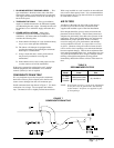
Condensate Drain Trap ............................................ 9
Air Filters ................................................................ 9
Wiring – Main Power.............................................. 10
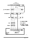
Wiring – 24V Low Voltage Control Circuit .............. 10
Transformer Taps ................................................... 10
Thermostats ........................................................... 10
Start Up and Operation
Three Phase Scroll Compressor Start Up
Information ..............................................................11
Sequence of Operation ...........................................11
Start Up Notes ........................................................11
High Pressure Switch and Lockout Relay ...............11
Service and Troubleshooting
Service Hints ......................................................... 12
Pressure Service Ports .......................................... 12
Refrigerant Charge ................................................ 12
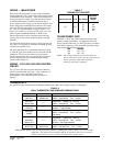
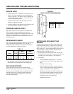
Fan Blade Settings................................................. 12
Suction and Discharge Tube Brazing ..................... 12
Pressure Table ....................................................... 13
Figures
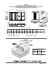
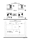
Figure 1 Prefabricated Rood Curb
Specifications .......................................... 5
Figure 2 Field Fabricated Curbing ......................... 5
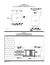
Figure3 Elevated Mounting Platforms .................. 7
Figure 4 Airflow and Service Access
Clearances .............................................. 7
Figure 5 Roof Top Application ............................... 8
Figure 6 Slab Mounting at Ground Level ............... 8
Figure 7 Condensate Drain Trap ........................... 9
Figure 8 Low Voltage Wiring ............................... 10
Figure 9 Fan Blade Setting Dimensions .............. 12
Figure 10 Brazing Diagram ................................... 13
Tables
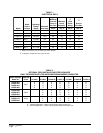
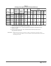
Table 1 Electrical Data ......................................... 2
Table 2 Optional Field Installed Heater
Packages ................................................ 2
Table 3 Optional Field Installed Heater Table ....... 3
Table 4 Maximum ESP of Operation ................... 4
Table 5 Rated CFM and Rated ESP.................... 6
Table 5A ESP in Inches H
2
O .................................. 6
Table 6 Air Filter Area and Size ........................... 9
Table 7 Thermostat Wire Size ........................... 10
Table 8 Wall Thermostat and Subbase
Combinations ........................................ 10
Table 9 Refrigerant Charge ............................... 12
Table10 Pressure Table ...................................... 13