


Manual 2100-346
Page 9
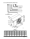
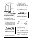
WIRING INSTRUCTIONS
GENERAL
All wiring must be installed in accordance with the National
Electrical Code and local codes. In Canada, all wiring must
be installed in accordance with the Canadian Electrical
Code and in accordance with the regulations of the
authorities having jurisdiction. Power supply voltage must
conform to the voltage shown on the unit serial plate. A
wiring diagram of the unit is attached to the inside of the
electrical cover. The power supply shall be sized and fused
according to the specification supplied. A ground lug is
supplied in the control compartment for equipment ground.
The unit rating plate lists a “Maximum Time Delay Fuse” or
HACR type” circuit breaker that is to be used with the
equipment. The correct size must be used for proper circuit
protection and also to assure that there will be no nuisance
tripping due to the momentary high starting current of the
compressor motor.
CONTROL CIRCUIT WIRING
For split systems, the minimum control circuit wiring gauge
needed to insure proper operation of all controls in both
indoor and outdoor units will depend on two factors:
1. The rated VA of the control circuit transformer.
2. The maximum total distance of the control circuit
wiring. (This is the distance between the wall
thermostat to the indoor unit plus the distance
between the indoor unit to the outdoor unit.)
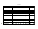
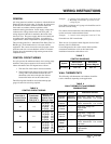
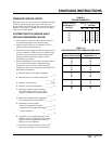
The following table should be used to determine proper
gauge of control circuit wiring required.
Example: 1. Control circuit transformer rated at 40 VA
2. Maximum total distance of control circuit
wiring 85 feet.
From Table 6, minimum of 18 gauge wire should be used in
the control circuit wiring.
For control circuit transformers rated other than those listed,
use the next lower rated transformer listed.
Example: 1. Control circuit transformer rated at 55 VA
From table use 50VA transformer.
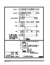
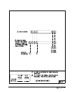
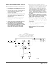
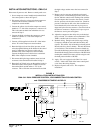
There are two (2) separate control diagrams for fossil fuel
furnaces with air conditioners.
Control diagrams for the various circuit which could be
encountered with blower coils can be found in the
installation instructions of the blower coil.
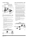
WALL THERMOSTATS
The following wall thermostats and subbases should be
used as indicated, depending on the application.
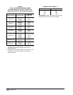
TABLE 7
CONTROL DIAGRAMS
metsyS
ecanruFsaG
margaiDlortnoC
ecanruFliO
margaiDlortnoC
sledoMllA001-1904101-1904
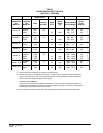
TABLE 8
WALL THERMOSTAT and SUBBASE
COMBINATIONS
tatsomrehTesabbuSserutaeFetanimoderP
200-3048
113F78T
300-4048
0221A925Q
yrucreM;loocegats1,taehegats1
otua-no:naFlooc-ffo-taeh:metsyS
140-3048
C-4308T
---
yrucreM;loocegats1,taehegats1
otua-no:naFlooc-ffo-taeh:metsyS
530-3048
08-59F1
---
loocegats2,taehegats2
elbammargorP
cinortcelE
240-3048
G1158T
---
loocegats1,taehegats2
looc-otua-ffo-taeh:metsyS
cinortcelEotua-no:naF
340-3048
002MC
---
loocegats1,taehegats1
otua-no:naFlooc-ffo-taeh:metsyS
noitcApanS
720-3048
17-29F1
---
loocegats2,taehegats3
elbammargorP
cinortcelE
TABLE 6
CONTROL CIRCUIT WIRING
foAVdetaR
tiucriClortnoC
remrofsnarT
remrofsnarT
yradnoceS
V42@ALF
latoTmumixM
foecnatsiD
tiucriClortnoC
teeFnigniriW
046.1
56eguag02
09eguag81
541eguag61
032eguag41
051.2
54eguag02
06eguag81
001eguag61
061eguag41
052eguag21
567.2
04eguag02
55eguag81
58eguag61
531eguag41
012eguag21