


Manual 2100-390
Page 7
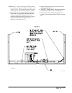
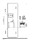
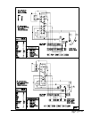
9. Connect lead with fork terminal to corresponding
points on terminal strip. Re.: C.Y.G. (See wiring
diagram.)
10. Wire nut leads with 5/8” stripped ends to Y1 and
Y2 leads from thermostat. See wiring diagram in
this manual or on economizer.
NOTE: Wires referenced in Note 1 on wiring
diagram are for special control application
only and are not normally used. These wires
may be used in conjunction with other
circuitry to open the damper regardless of
outside temperature and humidity. Consult
factory for details.
11. Close control panel cover
12. Reinstall the blower access panel at top of unit and
secure with sheet metal screws.
13. Replace filter bracket, filter and four (4) screws in
front condenser grille.
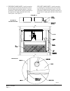
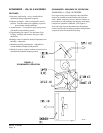
14. ECONOMIZER CHECK OUT
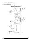
A. Remove mist eliminator (Figure 3). Locate the
minimum position potentiometer. (See Figure
5.)
B. Energize the evaporator blower by switching
thermostat to the manual fan position with
heat /cool in the OFF position.
C. Cycle the minimum position potentiometer
(factory set for 0% fresh air) 0 to full open. (See
Figure 5.) Throughout checkout procedure
observe operation of damper to insure there is
free, unobstructed operation through the entire
angle of damper travel. Then adjust the damper
minimum open position to meet local codes or
application requirements. See example below.
EXAMPLE:
1. Measure return air temperature (RAT)
(assume 75° F for example).
2. Measure outdoor air temperature (OAT)
(assume 60° F for example).
3. Calculate the mixed air temperature (MAT)
which will result from the desired
combination of OAT (10 percent) and RAT
(90 percent).
.1 OAT + .9 RAT = MAT
or substituting example values
.1(60° F) + .9 (75° F) = 73.75° F
4. Adjust the minimum position potentiometer
knob until proper mixed air temperature as
calculate above is reached. Care should be
taken to insure thermometer is sensing air
that is well mixed.
5. Mark correct setting on dial of minimum
position potentiometer for future reference.
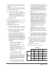
D. Adjust the enthalpy control to position A, B, C,
or D to achieve the maximum combination of
temperature and humidity acceptable for the
installation as per Table 2 below. The
suggested setting is between A & B 70° DB
@ 55 percent RH. It is further recommended to
always set the control at C or above. (See
Figure 5.)
E. Switch the thermostat fan control to automatic
and position, the heat cool switch to cool.
Adjust the thermostat temperature to engage the
first stage of cooling only (Y). This will cause
the dampers to modulate to achieve mixed air
temperature of 55° provided outside air
enthalpy is sufficiently low. If enthalpy is too
high for economizing, low enthalpy can be
simulated by temporarily removing and
jumping leads on terminal 2 and 3 of enthalpy
control together. This will also cause the
economizer damper to modulate away from
minimum position. (Be sure to properly
reconnect leads at end of checkout
procedure).
F. Readjust temperature on the thermostat to
engage the second stage of cooling (Y2). The
damper motor should return to previously set
minimum position. Compressor motor should
start.
G. Switch thermostat to OFF fan and OFF heat/
cool positions to de-energize unit. Economizer
damper should return to full closed (100 percent
return air) position. Checkout is complete.
15. Replace control access panel and mist eliminator.
16. Remove blank off plate or barometric fresh air
damper if installed on the service access panel.
Plug the four (4) holes used to mount the BOP or
BFAD with the plastic plugs supplied with the
economizer.
16. Replace service access panel.
17. Economizer is now ready for operation.
TABLE 2
laiD
gnitteS
%02
HR
%05
HR
%08
HR
yplahtnE
lortnoC
gnitteS
A
F.ged87
)C.ged62(
F.ged37
)C.ged32(
F.ged86
)C.ged02(
B
F.ged37
)C.ged32(
F.ged86
)C.ged02(
F.ged36
)C.ged71(
C
F.ged86
)C.ged02(
F.ged36
)C.ged71(
F.ged95
)C.ged51(
D
F.ged26
)C.ged71(
F.ged85
)C.ged41(
F.ged35
)C.ged21(