


Manual 2100-455A
Page 16 of 25
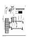
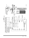
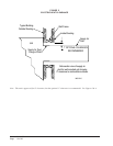
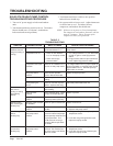
LOW VOLTAGE CONNECTIONS
FOR DDC CONTROL
Fan Only Energize G
Cooling Mode 1st Stage Energize Y, G
Cooling Mode 2nd Stage Energize Y, Y1, G
Heat Pump Heating 1st Stage Energize Y, G, B
Heat Pump Heating 2nd Stage Energize Y, Y1, G, B
3rd Stage Heating
Energize G, W2, Y, B, Y1
w/Heat Pump (if employed)
Ventilation Energize G, O1
Emergency Heat Energize B, W2, E, G
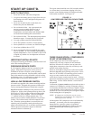
LOW VOLTAGE CONNECTIONS
These units use a grounded 24 volt AC low voltage
circuit and require at least a 2 stage heating and a 2
stage cooling thermostat.
The “R” terminal is the hot terminal and the “C”
terminal is grounded.
“G” terminal is the fan input.
“Y” terminal is the compressor Stage 1 input.
“Y1” terminal is the compressor Stage 2 input.
“B” terminal is the reversing valve input. The reversing
valve must be energized for heating mode.
“R” terminal is 24 VAC hot.
“C” terminal is 24 VAC grounded.
“L” terminal is compressor lockout output. This
terminal is activated on a high or low pressure trip by
the electronic heat pump control. This is a 24 VAC
output.
“W2” terminal is second stage heat (if equipped).
“O1” terminal is the ventilation input. This terminal
energizes any factory installed ventilation option.
“E” terminal is the emergency heat input. This terminal
energizes the emergency heat relay if equipped.
NOTE: For total and proper control using DDC, a
total of 7 controlled outputs are required (6 if
no ventilation system is installed). For proper
system operation under Emergency Heat
conditions where the compressor needs to be
deactivated, the B-W2-E outputs need to be
energized. Removing the Y (compressor) signal
alone turns the compressor off, but does not
activate the additional circuitry embedded in
the heat pump for proper and complete
operation.
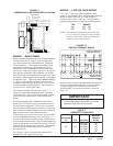
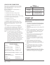
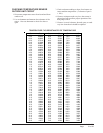
TABLE 4
WALL THERMOSTAT
tatsomrehTserutaeFtnanimoderP
940-3048
)083-39F1(
taeh.gts2;looc.gts2
cinortcelEelbammargorP
revoegnahclaunaMrootuA
250-3048
taeh.gts3;looc.gts2
cinortcelEelbammargorP
revoegnahclaunaMrootuA
START UP
These units require R-410A refrigerant & Polyol Ester oil.
APPLICATION:
1. Use separate service and manufacturing equipment
to avoid cross contamination of oil and refrigerants.
2. Use recovery equipment rated for R-410A
refrigerant.
3. Use manifold gauges rated for R-410A (800 psi/250
psi low).
4. R-410A is a binary blend of HFC-32 and HFC-125.
5. R-410A is nearly azeotropic - similar to R-22 and
R-12. Although nearly azeotropic, charge with
liquid refrigerant.
6. R-410A operates at 40-70% higher pressure than
R-22, and systems designed for R-22 cannot
withstand this higher pressure.
7. R-410A has an ozone depletion potential of zero,
but must be reclaimed due to its global warming
potential.
8. R-410A compressors use Polyol Ester oil.
9. Polyol Ester oil is hygroscopic; it will rapidly
absorb moisture and strongly hold this moisture in
the oil.
10. A liquid line dryer must be used - even a deep
vacuum will not separate moisture from the oil.
11. Limit atmospheric exposure to 15 minutes -
MAXIMUM.
12. If compressor removal is necessary, always plug
compressor immediately after removal. Purge with
small amount of nitrogen when inserting plugs.