


Manual 2100-404E
Page 9 of 19
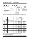
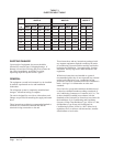
NOTE: The voltage should be measured a the
field power connection point in the unit
and while the unit is operating at full load
(maximum amperage operating condition.)
TABLE 4
OPERATING VOLTAGE RANGE
PATEGNAR
V042612–352
V802781–022
TABLE 5
THERMOSTAT WIRE SIZE
remrofsnarT
AVALFeguaGeriW
mumixaM
ecnatsiD
teeFnI
553.2
eguag02
eguag81
eguag61
eguag41
eguag21
54
06
001
061
052
TABLE 6
WALL THERMOSTAT
tatsomrehTserutaeFetanimoderP
750-3048
3511D0225HT
taeHegats1,looCegats1
elbammargorP-noNcinortcelE
revoegnahclaunaMrootuA
850-3048
1511D0225HT
taeHegats2,looCegats2
elbammargorP-noNcinortcelE
revoegnahclaunaMrootuA
060-3048
)544-0211(
taeHegats3;looCegats3
cinortcelEelbammargorP-noN/elbammargorP
lanoitnevnoCroPH
revoegnahclaunaMrootuA
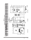
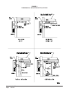
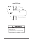
Five (5) wires should be run from thermostat subbase to
the 24V terminal board in the unit. A five conductor, 18
gauge copper, color-coded thermostat cable is
recommended. The connection points are shown in
Figure 8.
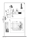
The electrical data lists fuse and wire sizes (75ºC copper)
for all models, including the most commonly used heater
sizes. Also shown are the number of field power circuits
required for the various models with heaters.
The unit rating plate lists a “Maximum Time Delay Relay
Fuse” or “HACR Type” circuit breaker that is to be used
with the equipment. The correct size must be used for
proper circuit protection and also to assure that there will
be no nuisance tripping due to the momentary high
starting current of the compressor motor.
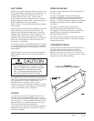
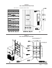
The disconnect access door on this unit may be locked to
prevent unauthorized access to the disconnect. To
convert for the locking capability, bend the tab located in
the bottom left hand corner of the disconnect opening
under the disconnect access panel straight out. This tab
will now line up with the slot in the door. When shut, a
padlock may be placed through the hole in the tab
preventing entry.
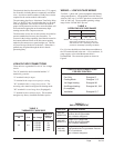
WIRING — LOW VOLTAGE WIRING
230/208V, 1 phase and 3 phase equipment dual primary
voltage transformers. All equipment leaves the factory
wired on 240V tap. For 208V operation, reconnect from
240V to 208V tap. The acceptable operating voltage
range for the 240 and 208V taps are:
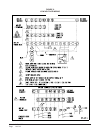
LOW VOLTAGE CONNECTIONS
These units use a grounded 24 volt AC low voltage
circuit.
The "R" terminal is the hot terminal and the "C"
terminal is grounded.
"G" terminal is the fan input.
"Y" terminal is the compressor input for cooling.
"W1" terminal is the 1st stage electric heat. The
reversing valve must be energized for heating mode.
"W2" terminal is second stage heat (if equipped).
"F" terminal is the ventilation input. This terminal
energizes any factory installed ventilation option.
LOW VOLTAGE CONNECTIONS
FOR DDC CONTROL
Fan Only Energize G
Cooling Mode Energize Y, G
1st Stage Heating Energize W1
2nd Stage Heating Energize W1, W2
(if employed)
Ventilation Energize G, F