


P/N 118000 rev. A 5
Banner Engineering Corp. • Minneapolis, MN U.S.A.
www.bannerengineering.com • Tel: 763.544.3164
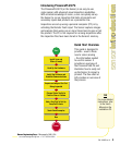
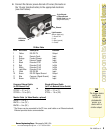
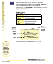
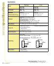
Light Connector
(Banner lights only)
1 = Brown 24V
2 = n/a
3 = Blue (ground)
4 = Strobe
Ethernet
NTSC Video
to Monitor
12-pin Discrete
I/O Power/Ground
RS-232 Serial (see pin
assignments below)
components/
connections
components/
connections
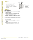
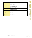
12-Wire Cable
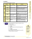
Pin # Wire Color Description Direction
1 Yellow RS-232 TX Output
2 Gray Remote Teach Input
3 Orange Product Change Input
4 Pink External Trigger Input
5 Black Discrete I/O #1 In/Out
6 Red Discrete I/O #2 In/Out
7 White Discrete I/O #3 In/Out
8 Light Blue Discrete I/O #4 In/Out
9 Violet RS-232 RX Input
10 Green RS-232 Signal Ground Output
11 Blue Common (Signal Ground) Input
12 Brown 10-30V dc Input
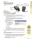
TIPS
The trigger device
can be any
10-30V dc
photoelectric
sensor, or a
device with a
similar output.
4. Connect the Sensor power-discrete I/O wires (the leads on
the 12-wire furnished cable) to the appropriate locations
(see chart below).
Crossover Ethernet Cable
(to PC Ethernet Port)*
STPX07 — 2.1 m (7')
or
STPX25 — 7.6 m (25')
Monitor Cable (to Video Monitor, optional)
BNC06 — 2 m (6')
BNC15 — 5 m (15')
BNC30 — 9 m (30')
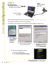
* The Sensor can be connected to the PC via a serial cable or an Ethernet network;
Ethernet provides faster communication.
Standard Ethernet Cable
(to PC via Network Hub or Switch)
STP07 — 2.1 m (7')
STP25 — 7.6 m (25')