


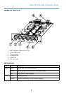
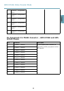


AXIS Q7436 Video Encoder Blade
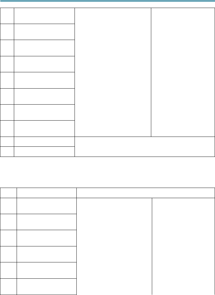
3
Channel 1, Congurable
I/O 1
4
Channel 2, Congurable
I/O 1
5
Channel 3, Congurable
I/O 1
6
Channel 4, Congurable
I/O 1
7
Channel 5, Congurable
I/O 1
8
Channel 6, Congurable
I/O 1
9
Channel 1, Congurable
I/O 2
10
Channel 2, Congurable
I/O 2
Digital input - Connect to GND
to activate, or leave oating (or
unconnected) to deactivate.
Digital output - Uses an open
drain NFET transistor with the
sourceconnected toGND.If used
with an external relay, a diode
must be connected in parallel
with the load, for protection
against voltage transients.
Min input = – 40 V DC
Max input = + 40 V DC
Max load = 100mA
Max voltage = + 40 V DC
(to the transistor)
11
RS485A
12
RS485B
A half-duplex RS485 interface for controlling auxiliary
equipment such as PTZ devices.
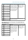
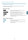
Pin assignments for the I/O Connector of the AXIS Q7900 and
AXIS Q7920 Chassis
Pin Function Description
1
Channel 1, Congurable
I/O 1
2
Channel 2, Congurable
I/O 1
3
Channel 3, Congurable
I/O 1
4
Channel 4, Congurable
I/O 1
5
Channel 5, Congurable
I/O 1
6
Channel 6, Congurable
I/O 1
Digital input - Connect to GND
to activate, or leave oating (or
unconnected) to deactivate.
Digital output - Uses an open
drain NFET transistor with the
source connected to GND. If
used with an external relay,
a diode must be connected
in parallel with the load, for
protection against voltage
transients.
Min input = – 40 V DC
Max input = + 40 V DC
Max load = 100mA
Max voltage = + 40 V DC
(to the transistor)
10