


6. WATER SUPPLY - Required Criteria
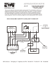
9. WIRING THE STEAM HUMIDIFIER
IMPORTANT: Dedicated fused circuits of the proper
voltage and current ratings must be provided. All
wiring must conform to local and national codes.
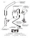
7. M OUNTING THE STEAM HUMIDIFIER
8. STEAM OPERATION
A. WATER SUPPLY USING THE SADDLE VALVE
FURNISHED WITH UNIT
A. INSTALLING AND WIRING THE HUMIDISTAT
B. FIELD WIRING
IMPORTANT NOTE:
B. OVERFLOW & DRAIN LINES - Required Criteria
Installation instructions for the saddle valve are printed on
the plastic bag containing the saddle valve and its
components. Tap into a 1/2” or 3/4” domestic hot water
line for best results, but a cold water line will do. Avoid
connecting to water lines from a Reverse Osmosis system.
The supply water must read a minimum of 25 ppm in
order for the Steam unit to reliably sense the water.
NOTE: Never install the saddle valve on the bottom of the
water pipe. Sediment in the water pipe may clog the
saddle valve. When tightening the hex compression nut,
tighten only enough to assure there are no leaks.
NOTE: Saddle valves do not meet plumbing codes in
some areas. A “T” fitting with a valve may be required to
meet code or, if low water pressure causes frequent water
alerts on the steam humidifier.
NOTE: Do not use any line which is served by a water
softener. If your home has a water softener, make the
water connections to a water line upstream from the water
softener. A water softener is not a demineralizer. It merely
exchanges various hard ions for soft ions in the water.
These soft ions, or minerals, will build up in the
humidifier, causing the need for frequent servicing. The
evaporation of softened water may also produce a white
powder which may be carried into the duct system and,
ultimately, into your home.
Note: Use a water hammer arrester (WH-100)
if water spikes occur during operation.
A temperature sensor is mounted in the water reservoir of the
humidifier. As the water temperature increases to about 170
degrees F, the computer closes a set of blower relay contacts.
When the water cools to about 140 degrees F, the computer
will open the relay contacts.
A humidistat, such as the AutoFlo Models 062000 or
072000 is required to control the Steam Humidifier. The
humidistat may be installed on the wall in the living space
or on the return air duct. NOTE: Continuos fan operation
should be initiated if the humidistat is installed on the
return air duct! Instructions for installation are packaged
with the humidistat.
DO NOT connect any foreign voltage to the “H” terminals
of the humidifier. The unit supplies it’s own 24 volt
control voltage. Simply connect the two “H” terminals
straight to the humidistat terminals.
All wiring must be made in accordance with local
codes and ordinances. DO NOT cut off the
grounded plug and/or hard wire this unit to line
voltage. Do not use extension cords to
operate this unit!
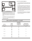
Figures 5 & 6 describes the suggested interlock
wiring arrangement for HVAC systems. Interlocking
may be performed on heating systems that provide a
24 VAC NEC Class 2 terminal for blower control.
If the Steam Humidifier is removed and
disconnected from the system, the
blower interlock circuit must be
restored to it's original configuration.
Failure to do so may result in loss of
blower operation!
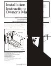
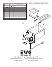
Use gaskets to seal where the steam flanges contacts the
ductwork. Place the humidifier reservoir into the opening in
the duct and secure with eight (8) sheet metal screws.
NOTE: If the ductwork will not support the unit in a level
position with the water pan full of water, the duct-work
must be reinforced. Both steam models weigh
approximately 9 Lbs. empty and approximately 15 Lbs.
full of water.
Because of the high output of this Humidifier, it must not
be operated in ducts or plenums without the blower
operating. The steam humidifier is designed to be
"Dominant" over the Heating-Air Conditioning System
Blower. The "System" Blower will be operated by the
humidifier, when humidity is required to meet the
demand. A minimum of 800 cfm is required for proper
operation of the steam humidifier. Lower velocities will
result in excessive condensation inside the duct.
The use of an overflow line and drain line is always
required.
Use the supplied 1/2” ID high temperature hose. Slip the
hose over the 1/2” OD “T” drain fitting and use a hose
clamp to secure. Route the hose to a suitable drain,
avoiding kinks, traps and sharp objects.
DO NOT route the hose above the humidifier.
NOTE: Previous models required two [2] drain hoses.
The new models include an integrated overflow tube with
a high temperature barbed “T” fitting. The new design
simplifies the installation process.
Failure to install all necessary drain lines will result in
water leaks during normal operating conditions, and
voids all warranties.
3
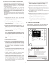
S2000 & S2020 Typical Wiring
and Blower Interlock Diagram
Furnace
S2000 & S2020 Humidifier
Humidistat
G1 R G2 H H
Typical
Thermostat
G YWR
G YWR
FIG. 5
Heat & Cool System