System 10 Portable Camera-Mount Wireless Installation and Operation
3
Receiver Installation
Location
For best operation the receiver should be at least 3' (1 m) above the
ground and at least 3' (1 m) away from a wall or metal surface to minimize
reections. Keep the receiver antennas away from noise sources such
as other digital wireless equipment, microwave ovens, as well as away
from large metal objects. Keep System 10 receiver 30' (9 m) away from
wireless access points. In multi-channel systems, position receivers at
least 3' (1 m) apart and keep operating transmitters at least 6' (2 m) from
the receivers to help assure maximum RF performance.
Output Connection
The ATW-R1700 has a single audio output jack that accepts the 3.5 mm
(
1
/
8
") cable included in the package.
Use the Audio Output Selector Switch to choose between a balanced
and an unbalanced dual mono signal.
The 3.5 mm (
1
/
8
") Headphone Monitor output works with mono or stereo
headphones (the output sends a dual mono audio signal to stereo
headphones). Use the Headphone Level Control to adjust the volume.
Power Connection
NOTE: Use only the supplied AC adapter and power cord to power or
charge receiver. To use AC power, connect the power cord’s USB A-type
male port to the AC adapter and connect the Micro-USB B port to the
USB Power Input on the side of the receiver. Next, plug the adapter
into a standard 120 Volt 60 Hz or 230 volt 50 Hz (depending on global
location) AC power outlet. The AC adapter and USB cable also charges
the receiver’s internal battery. Charge battery in an environment with
moderate temperature (41°F – 95°F). The system will not charge in
temperatures below 32°F or above 104°F in order to prevent potential
damage to battery. For safety and to conserve energy, unplug the
AC adapter from the AC outlet when the system is not in use. Store
receiver in a cool place.
Antennas
For best reception, position the removable antennas in the shape of a
“V” so that both tilt 45°.
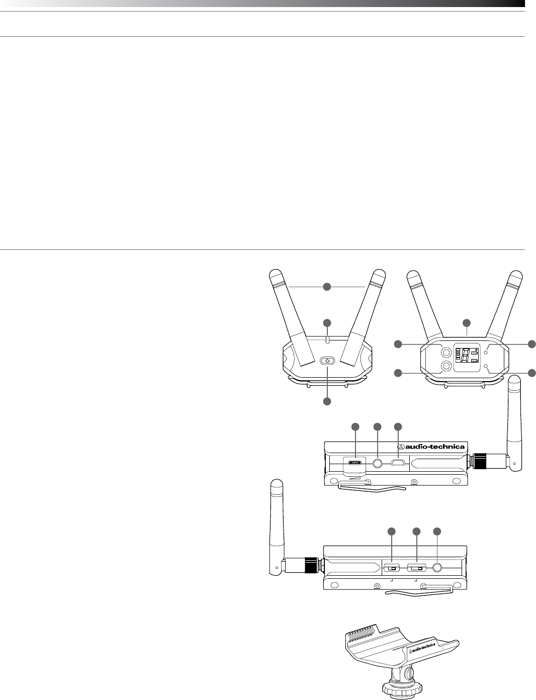
ATW-R1700 Receiver Controls and Functions
Figure A — Front Panel Controls and Functions
1. Removable Antennas: Position the antennas as shown.
2. Power/Battery Indicator: Glows green when receiver is on and
battery is charged. Flashes green when battery needs to be
charged. Glows red when battery is charging.
3. Power Switch: Press and hold to turn receiver on or off.
Figure B — Rear Panel Controls and Functions
4. System ID Select Switch: Press to cycle through System ID
numbers. (System ID is the identical number assigned to a paired
receiver and transmitter.)
5. Pairing Switch: Press to initiate pairing
6. LCD System Display contains:
a. RF Signal Level Indicator: shows strength of the RF signal
received from the transmitter
b. The System ID Display: shows the System ID number
c. The Receiver Battery Gauge RX: shows the capacity of the
receiver’s internal battery/charging status
d. The Transmitter Battery Gauge TX: shows the capacity of the
transmitter’s batteries
7. AF Peak Indicator: Only lights when audio distortion is present at
maximum modulation. Attenuator does not affect the indicator.
8. Pairing Indicator: Flashes green in pair mode. Glows green when
transmitter is paired.
Figure C — Right Side Controls and Functions
9. Headphone Level Control: This control is used to adjust the volume
of the signal sent to the headphones. Roll control to the right to
increase the volume.
10. Headphone Monitor: Accepts 3.5 mm (
1
/
8
") connector. Plug in
either a mono or stereo headphone to monitor receiver signal.
11. Power Input: Connect the AC Power Supply adapter included in
the system to charge/operate the receiver.
Figure D— Left Side Controls and Functions
12. Audio Output Selector Switch: Move left for balanced output or
right for unbalanced (dual mono) output.
13. Audio Output Attenuator Switch: Default is 0 dB. Move one stop left
to reduce he audio output by 10 dB or two stops left to reduce
output by 20 dB.
14. Audio Output Jack: TRS balanced or unbalanced (dual mono)
3.5 mm (
1
/
8
") jack. Can be connected to the input of a camera or mixer.
Figure E— Camera Shoe Mount
Camera Shoe Mount allows receiver to be attached to a camera or tripod.
Slide mount onto receiver from the rear so mount engages the grooves
on the sides of the receiver and slips under the clip on the bottom. Slide
until rear of mount is ush with rear of receiver. The mount bracket
PEAK
RX
TX
RF
SYSTEM
ID
PAIRPAIR
MONITOR CHARGE
OUTPUT
DUAL MONO
|
BAL ATT. -20
|
-10
|
0
DUAL MONO
|
BAL ATT. -20
|
-10
|
0
1
2
9
12
10
13
11
14
6
3
Figure A
Figure C
Figure D
Figure E
Figure B
4 7
5 8
connects to the hot shoe of most DSLR cameras: slide into shoe and
tighten nut to secure. The bracket’s ¼" socket also allows it to be attached
to a tripod, shoulder rig or other device with a ¼" screw.


