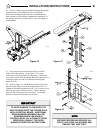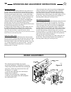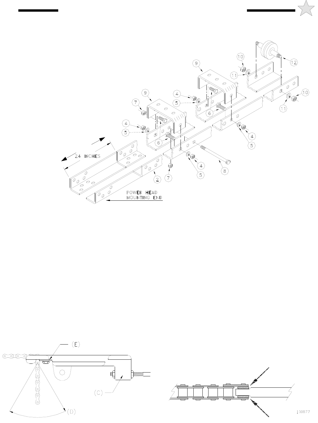
2) After the track is assembled, position track assembly onto
the operator power head and attach with four 3/8”-16 x 1” bolts,
lock washers and nuts (supplied in a separate hardware package
#100470).
NOTE: To keep #41 chain (used
on 1/2 and 3/4 H.P. operators) centered
on the threaded stud, place a .065" thick flat
washer (provided) on each side of the flat, as
indicated by the arrows in Figure 4, when installing
the connecting link. One-third horsepower operators use the
narrower #65 chain and the use of the spacers is not required.
Install chain around drive sprocket at operator head then around
idler at front end of rail and thread through opening at front end
of carrier. If the rail is equipped with a chain guide-spacer near
its center (12 foot rail or longer only) pass the chain over it in one
direction and under it in the other direction to separate the two
lengths of chain. Apply initial tension by pushing forward on the
carrier while pulling chain tight through opening in the carrier in
the direction of D. When maximum tension has been applied by
this means, swing chain forward and insert retaining plate, E, in
place. Insert 1/4-20 x 5/8 hex head machine screw through
retaining plate, E, and tighten plate in place. Make final
adjustment of chain tension to remove excess sag by adjusting
nuts on threaded rod at chain lug, C.
RAIL/CHAIN ASSEMBLY
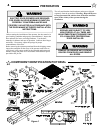
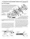
Refer to Figure 1 parts illustrations. The part names and item numbers are
referenced identically to the part names and numbers in the assembly procedures
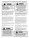
that follow. Before starting assembly of the operator track check for the
proper length. The tracks are supplied for 8 Foot, 10/12/14 Foot,
16/18 Foot and 20/22 Foot high doors. The tracks should be
three (3) feet longer than the door height. If the tracks
supplied with the operator are longer than the door
height plus 3 feet, it will be necessary to cut off two
feet (or 4 feet for 10 Foot rail) from the power head
mounting end as shown in Figure 2.
CAUTION
: WHEN NECESSARY TO
CUT THE TRACK ENSURE THE
ENDS ARE LINED UP AS IN
FIGURE 2.
1) Assemble the
operator track by
assembling the items
as shown in Figure 2.
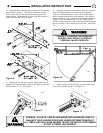
3) Referring to Figure 1 , 2 and 3 (below) , slide the trolley
onto the track with the chain take up bolt lug (C) toward the
power head. Thread one 3/8-16 keps nut (attached star washer)
onto the Chain take up bolt with the keps part (attached star
washer) away from the chain attachment end. Insert the chain
take up bolt threaded end through the lug hole on the trolley (C)
just far enough to start a second 3/8-16 keps nut. Attach one end
of the chain to the opposite end of the threaded stud using a 3-
piece chain link (provided). See Figure 3.
Figure 3
100461
Figure 4
Figure 2
107068
48” FOR 10FT RAIL
6
RAIL/CHAIN ASSEMBLY INSTRUCTIONS


