


TH146-P-DE 400-280-004-C 11/29/06 2/9
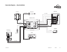
• Controller terminal L to heat pump terminal L
• Controller terminal W to heat pump terminal W (see section
2.5)
• Controller terminal G to heat pump terminal G (see section
2.5)
You might need a 24 V transformer if you have an add-on installa-
tion. Connect the transformer to the controller terminals R and C (24
Vac In).
If you have an add-on installation, you might need a relay such as
Aube’s RC845 to connect the furnace (auxiliary heating) and its fan
to the controller. Install the relay near the control module. Connect
the wires of the RC845 relay as follows:
• relay terminals W, G and C to controller terminals W, G and
C.
• relay terminals T and T to the appropriate furnace terminals:
T and T (oil); TH and TH (gas); R and W (electric).
NOTE: Refer to the relay’s installation instructions for more details.
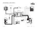
Connect the humidifier to controller terminals C and H (no polarity).
The outdoor sensor is required for the following:
• balance points
• automatic humidity control
• outdoor temperature display
• defrost point
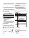
When installing the sensor, observe the following guidelines:
• Avoid locations where the sensor can be covered with snow
or exposed to direct sunlight.
• Avoid air outlets and concealed chimneys or stove pipes.
Install the sensor using its mounting clip and connect it to controller
terminals OS and CS (no polarity).
NOTE: The maximum wire length is 30 m (100 feet).
The plenum sensor measures the temperature inside the plenum.
This data is required for high pressure protection during the defrost
cycle (see section 4.3).
NOTE: The plenum sensor is generally needed for add-on installa-
tions only. It is not needed if the heat pump is not connected to the
controller terminal WW.
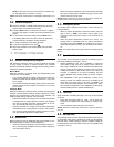
Install the sensor on the side of the plenum and
position it such that its aperture faces the air
flow.
Connect the sensor to controller terminals PS
and CS (no polarity). For more information,
refer to the instructions provided with the sen-
sor.
NOTE: The maximum wire length is 30 m (100
feet).
The dual-energy input can be connected to the dual-register meter
equipped with a normally open (NO) dry contact. Connect the termi-
nals DE and CC of the controller to the terminals (yellow and red
wires) of the dual-register meter.
When the contact is open, the heat pump and auxiliary heating
operate as usual. The contact closes when the outdoor temperature
drops below the set threshold. When the contact is closed, the heat
pump is disabled and only the auxiliary heat can be used.
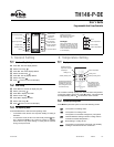
To use the unoccupied mode, the controller requires a remote con-
trol device such as Aube’s telephone controller CT241 equipped
with a dry-contact output (normally open). The unoccupied mode is
activated when the contact closes. (See section 6.4.)
To access the 2 configuration switches, loosen the captive screw
under the console and separate the console from its base by pulling
the bottom section.
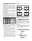
3.1.1 Keypad Lock (SW1)
I: The keypad is locked. Settings cannot be changed.
O: The keypad is unlocked.
3.1.2 Access Mode (SW2)
INST: Installer mode. Gives access to all configuration parameters.
2.4
24 V Transformer
2.5
RC845 Relay
2.6
Humidifier
2.7
Outdoor Sensor (AC144-03)
2.8
Plenum Sensor (AC146-410)
2.9
Dual-energy Input
2.10
Unoccupied Mode Input
2.11
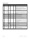
Wiring Table
24 Vac In
R
C
Power; 24 Vac
Thermostat
TH
TH
Console connection
Plenum
Sensor
PS
CS
Plenum temperature sensor connection
Outdoor
Sensor
OS
CS
Outdoor temperature sensor connection
Dual Energy
DE
CC
Dual energy connection
(requires a normally open contact)
Unoccupied
UN
CC
Unoccupied mode connection
(requires a normally open contact)
Heat Pump
R
C
Power; 24 Vac / 3 A
Y Output; 24 Vac / 1 A (compressor)
O/B
Output; 24 Vac / 1 A
(reversing valve; energized on cool)
WW Input; 24 Vac / 2 mA (defrost)
L Input; 24 Vac / 2 mA (fault)
Aux. Heat
W
G
Output; 24 Vac / 1 A (auxiliary heat and fan)
Humidifier
C
H
Output; 24 Vac / 1 A
3. Configuration
3.1
Switch Configuration