


TH146-N-U 8/12
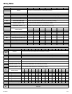
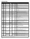
Configuration Menu
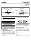
Item HP HVAC Parameters Display Options Default Description
1 Temperature format °C / °F °C Select the temperature display format.
2* Balance point low
-30 to 10°C
(-22 to 50°F)
-10°C
(14°F)
Set the bP L limit (see section 4.2).
NOTE: Lower bP L below its minimum (- -) if you do not wish to use this
function.
3* Balance point high
-5 to 30°C
(23 to 86°F)
5°C
(41°F)
Set the bP H limit (see section 4.2).
NOTE: Raise bP H above its maximum (- -) if you do not wish to use this
function.
4* Defrost point
-10 to 15°C
(14 to 59°F)
10°C
(50°F)
Set the defrost point temperature (see section 4.3).
NOTE: Raise the defrost point above its maximum (- -) if you do not wish to
use this function.
5* Installation type Ad / nr Ad
Set according to the type of heat pump installation (see section 4.4).
• Ad (add-on): Use this setting when the indoor coils are located down-
stream of the auxiliary heat source. This is generally the case for add-on
installations.
• nr (normal): Select this setting when the indoor coils are located
upstream of the auxiliary heat source. This is generally the case for new
installations.
6*
Auxiliary
interstage delay
5 to 90 min. 30 min. Set the interstage delay for the auxiliary stage (see section 4.5).
7 Low temperature limit
-10 to 20°C
(14 to 68°F)
- -
Set the low temperature limit of the plenum (see section 4.6).
NOTE: This function is not used if you lower LLMT below its minimum (- -)
or if the plenum temperature sensor is not connected to the controller.
8 High temperature limit
30 to 90°C
(86 to 194°F)
- -
Set the high temperature limit of the plenum (see section 4.6).
NOTE: This function is not used if you raise HLMT above its maximum (- -)
or if the plenum temperature sensor is not connected to the controller.
9 Cycles per hour 2 to 6 4
Select the number of heating/cooling cycles per hour. For optimal heating
control, use the setting that matches your system as follows: 3=20 min (hot
water, 90%+ high-efficiency furnace), 4=15 min (gas or oil), 5=12 min (gas
or oil), 6=10 min (electric).
10 Heat type GA / EL EL
This setting determines the fan operation in automatic mode when the sys-
tem is in heating mode (see section 5.2).
• EL (electric heating): The fan starts when heating starts and stops when
heating stops.
• GA (gas or oil heating): The fan starts when the temperature inside the
plenum rises above the Fan Limit (see item 11) and stops when the tem-
perature drops 12°C below the Fan Limit. Note: The fan will not start if
the plenum temperature sensor is not connected to the controller.
11 Fan limit
38 to 90°C
(100 to 194°F)
80°C
(176°F)
This parameter is available only when gas heating is selected (see item 10).
WARNING: FLMT can be used in parallel with an UL353-approved
device but they do not replace such device.
NOTE: The fan will not start if you raise FLMT above its maximum (--).
12 Smart Fan On / OF OF
• On: Smart Fan is On (see section 4.7).
• OF: Smart Fan is Off.
13 Temperature setback
0 to 9°C
(0 to 16°F)
0°C
(0°F)
Set the amount of temperature setback when the controller is placed in
Unoccupied mode (see section 5.6).
14
Outdoor temperature
display
On / OF On
Select between displaying the outdoor temperature or the indoor humidity
level.
• On: Displays the outdoor temperature.
• OF: Displays the indoor humidity level.
NOTE: To display the outdoor temperature, the outdoor sensor must be
connected.
15
Humidifier
operating mode
Co / HE / Fn HE
• Co (conventional): The humidifier will operate if the humidity is too low. If
the fan is not already On, it will turn On at the same time as the humidi-
fier.
• HE (heat): The humidifier can operate only when heating is activated.
• Fn (fan): The humidifier can operate as long as the fan is running,
whether heating is activated or not.
NOTE: The humidifier is disabled when cooling is activated.
16
Automatic humidity
adjustment
On / OF OF
Allows you to set the humidity control to automatic mode.
• On (automatic): The humidity level is automatically regulated by the con-
troller according to the outdoor temperature to avoid condensation or ice
formation on windows while providing enough humidity for your comfort
(see item 17).
• OF (manual): The user manually sets the humidity level (see item 17).
17**
Humidity setpoint 5 to 60% 5 %
Set the desired humidity level. This parameter is available only when the
humidity control is placed in manual mode (see item 16).
Humidity offset -9 to 9% 0
This parameter is available only when the humidity control is placed in auto-
matic mode (see item 16). It allows the user to apply an offset to the auto-
matic humidity control. For example, the user can enter a negative offset if
there is ice formation or condensation on the windows.
* Parameters 2 to 6 are not available when the controller is configured for 1H1C, 2H2C or 3H3C heat pump.
** Only parameter 17 is available when the controller is in user mode (SW1-2 switch).