


PB130 400-130-001-E 19/9/05 1/1
The PB130-230 power base is used to power a TH13x Series control
module. The resistive load must not exceed 3450 watts (NI) @
230 VAC (15 A).
n One (1) PB130-230 power base
o One (1) floor sensor (for AF and F control modules only)
p One (1) wall plate (optional, in certain countries)
Turn off power to the heating system at the main power panel to avoid
electrical shock. Installation should be carried out by an electrician.
All work must conform to the applicable country standards for
electrical installations and wiring.
This thermostat should be connected on a circuit equipped with
a fuse or a circuit breaker. It must be installed on a certified
electrical box.
For a new installation, choose a location about 1.5 m above the
floor.
For electric baseboards, convectors and fan-forced heaters, the
thermostat must be installed facing the heating system.
The thermostat must be installed on an inside wall.
Avoid locations where there are air drafts (top of staircase, air
outlet), dead air spots (behind a door), direct sunlight or
concealed chimneys or stove pipes.
Model: PB130A-230
Supply: 230 VAC, 50 Hz
Load: 15 A maximum (resistive only)
Power: 3450 Watts (NI) @ 230 VAC
Conformity: EN60730-2-9 / EN50081-1 / EN50082-2
Storage: -20°C to 50°C
Protection: Class 2
Protection degree:IP21
Automatic action: Type 1.B
Environment: Normally polluted
Size (H•W•D): 2.95 x 2.95 x 0.55 in. (75 x 75 x 14 mm)
NOTE: The terminals are designed to handle a cross-section of wire
measuring 0.33 to 3.1 mm
2
.
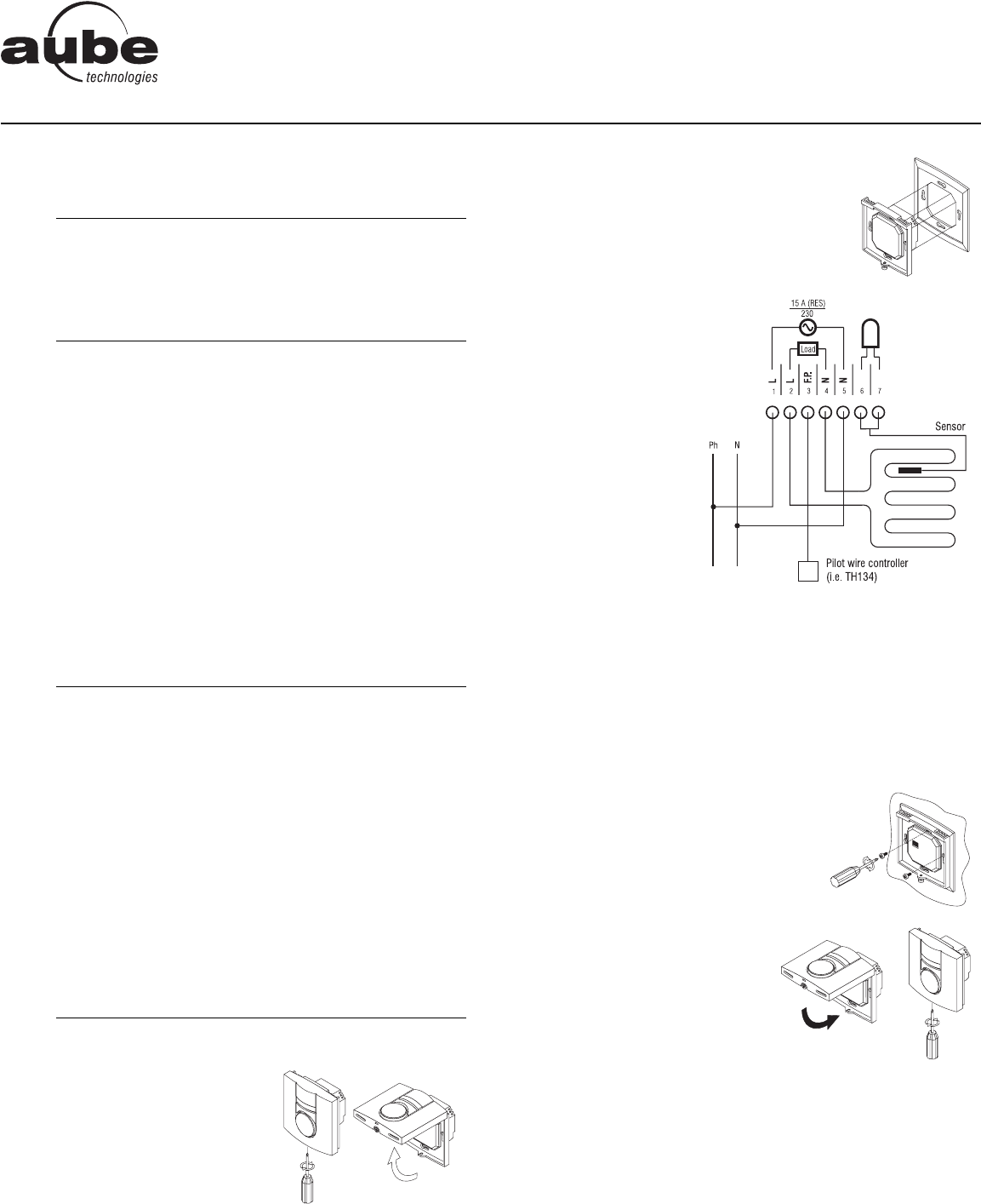
n Remove the screw holding the
control module to the power base
and lift the lower part upwards.
The screw cannot be completely
removed.
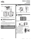
o Before making the connections, make sure
that the base covers the electrical box
entirely. If not, install a wall plate at the
back of the base as shown.
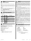
p Connect the wires:
• Power:
Terminals 1 & 5
• Load:
Terminals 2 & 4
see note 1
• Pilot Wire:
Terminal 3
see note 2
• Floor sensor:
Terminals 6 & 7
(no polarity)
see note 3
Note 1 If a contactor is used between the thermostat and the load,
install a snubber at the contactor’s coil terminal to ensure
the proper operation of the thermostat.
Note 2 This connection is required on some models only.
Note 3 For the proper operation of the thermostat, the floor sensor
must be centered between two heater wires having a
maximum temperature of 80°C. The floor sensor wire must
not cross any heater wire or be placed close to it.
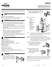
r Push wires into the electrical box and
secure the base to the electrical box
anchorage. The head of the screw
must be less than 2 mm thick.
s BEFORE installing the control
module onto the base, set the
configuration switches (if any)
on the control module (refer to
the user guide).
WARNING: This power base must be used only with 15-minute
heating cycles. If your control module has a selector switch for
choosing the heating cycle, ensure that the switch is correctly set.
t Return power to the heating system.
n
Parts
1.
o
Guidelines
2.
p
Technical Specifications
3.
q
Procedure
4.
PB130
Installation Instructions
230 V Line Voltage Power Base