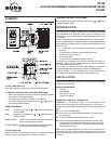
WARNING: After removing the wall plate, if you find that it is
mounted on a junction box (e.g. a box similar to one behind a light
switch or electric outlet), 240 volts circuit may be present and there
is a danger of electric shock. Please consult a qualified electrician.
WIRE LABELLING
n If your old thermostat wall plate has more than two wires con-
nected to it, then you will need to label the wires. First look for
LETTER near each terminal where a wire is connected. These
terminals and markings may be on either side of the wall plate.
o Disconnect and identify each wire.
p You may wish to tape the wires to the wall to keep them from
slipping through the hole in the wall. If the hole in the wall is
larger than necessary, fill it in order to prevent hot or cold air to
penetrate the thermostat. In this manner, the thermostat will
behave perfectly.
CHOOSING A LOCATION
Note: For a new installation, choose a mounting location about five
feet (150 cm) above the floor in an area with good air circulation and
away from:
Drafts or dead air spots, Air ducts, radiant heat from the sun or
appliances, Concealed pipes and chimneys.
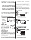
Mounting the thermostat onto the wall
n Remove completely the slide door of the thermostat.
o Unscrew and remove the cover over the connector.
p Mark the holes posi-
tion and align the wire
coming from the wall
in the hole beside the
connectors.
q Drill two holes and
insert the plastic
anchors carefully into
the holes until they are
flush with the wall.
r Fasten securely the thermostat to the wall with the two (2)
screws.
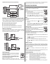
DISPLAY IN °C OR °F
After the installation of the battery, if
you want to change unit of the degree
displayed, follow these instructions
(see the illustration):
n From the back of the thermostat,
unscrew the cover.
o For the °C display, the jumper in
JP1 is installed.
p For the °F display, the jumper in JP1 is removed.
q Re-install the cover in place.
r Press on the reset button.
CONNECTING THE LABELLED WIRES TO THE THERMO-
STAT
n Connect the system wires to the terminals according to the wir-
ing diagram shown in the section “wiring diagram”.
WARNING: Do not remove the jumper between terminals Rh and
Rc unless otherwise specified.
o Push on the wires in the wall and replace the cover over the
connectors.
p Install two (2) “AA” size batteries into the battery compartment.
q Turn on the main switch of the system. The thermostat is ready
for use.
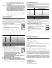
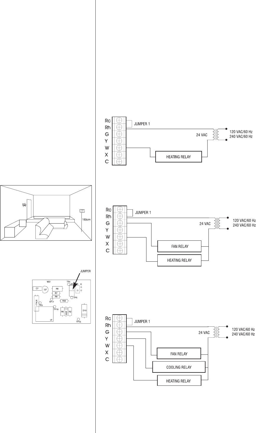
WIRING DIAGRAM
The TH123 thermostat can be used with any single stage heating
and cooling system. You cannot directly use this thermostat on mul-
tiple stages heating or cooling system, millivolt system, heat pump
or 240 VAC control system. It can control some of those systems by
installing an isolation relay and a 24-volt transformer.
HEATING SYSTEM TYPE
The heating system type selector is located below the wire connec-
tor. Start first by keeping the selector at default position Hg. If the
fan switch is at FAN AUTO position and the fan doesn’t start when
the thermostat turns on the furnace, place the type selector at posi-
tion He.
2-WIRE HEATING SYSTEM
n Connect the heating relay to terminal W.
o Connect the 24 VAC transformer to terminal Rh.
3-WIRE HEATING SYSTEM WITH FAN CONTROL
n Connect the heating relay to terminal W.
o Connect the fan relay to terminal G.
p Connect the 24 VAC transformer to terminal Rh.
4-WIRE HEATING AND COOLING SYSTEM
n Connect the heating relay to terminal W.
o Connect the cooling relay to terminal Y.
p Connect the fan relay to terminal G.
q Connect the 24VAC transformer to terminal Rh.


