


PB112B 400-112-028-B 16/3/07 1/2
This power base has been designed for floor heating applications. It
has ground fault protection (GFCI
1
or EGFPD
2
) and an input for
connecting a floor sensor.
If your thermostat has the Vacation Mode, the mode can be activated
by connecting an Aube telephone controller (CT240 or CT241) or any
other remote control device equipped with a normally open (NO) dry
contact. For more information on this mode, see the thermostat’s
user guide.
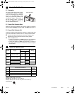
NOTE: This power base must be used with thermostat operating on
15-minute cycles.
1
Ground Fault Circuit Interrupter
2
Equipment Ground Fault Protection Device
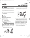
n One (1) power base
o Two (2) screws
p Four (4) solderless connectors for copper wires
NOTE: Special CO/ALR solderless connectors must be used for con-
necting aluminum conductors.
q One (1) floor sensor
r One (1) flat-tip screwdriver
Install the thermostat onto an electrical box.
Do NOT install the thermostat in an area where it can be
exposed to water or rain.
Installation should be carried out by an electrician and must
comply with local electrical codes.
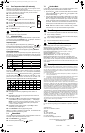
n Turn off power to the heating system at the main power panel in
order to avoid any risk of electrical shock.
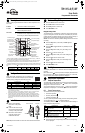
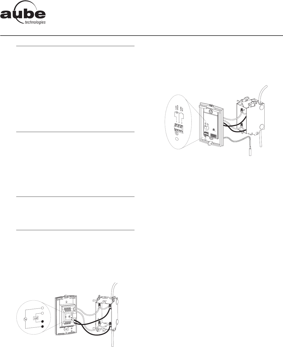
o Connect the power base wires to the power supply and to the
load using solderless connectors for copper wires.
p Insert the floor sensor cable through one of the two openings on
the base and connect the sensor wires to terminals 1 and 2 (no
polarity).
Position the sensor cable such that it does not come in contact
with the floor heating wires. The sensor probe must be centered
between two floor heating wires for best temperature control.
q If you wish to connect a remote control device, insert the wires
(use 18- to 22-gauge flexible wires) through one of the two open-
ings on the base and connect them to terminals 2 and 3 (no
polarity).
r Push the excess length of the high-voltage wires back inside the
electrical box.
s Secure the power base to the electrical box using the provided
screws.
t Verify the settings of the configuration switches (if any) on the
back of the control module (see user guide).
u Install the control module on the base (see user guide).
v Apply power to the heating system. Verify the installation by
making sure that the heating system can be turned on and
turned off by increasing and decreasing the setpoint.
w Test the ground fault protection.
n
Applications
1.
o
Supplied Parts
2.
p
Installation Guidelines
3.
q
Installation Procedure
4.
Load
Power supply
Floor
temperature
sensor
PB112B
Installation Instructions
For models: 120GA / 120GB / 240GA / 240GB
400-112-028-B (PB112B with GFCI) ENG.fm Page 1 Friday, March 16, 2007 1:52 PM