This thermostat has been designed to control a RESISTIVE load
not exceeding 3500 W @ 240 VAC or 1750 W @ 120 VAC, such as
electric baseboards, convectors, radiant ceilings, floor heating sys-
tems, etc.
It is not compatible with a low voltage controller used by a cen-
tral heating system or systems using a contactor or a relay
whose current is under 2 A.
TURN OFF POWER TO THE HEATING SYSTEM AT THE
MAIN POWER PANEL TO AVOID ELECTRICAL SHOCK.
Installation should be carried out by an electrician.
This thermostat is designed to be used with a self-pro-
tected heating system equipped with linear limit control
and circuit breaker.
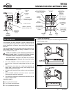
For a new installation, choose a location about 5 ft. (1.5 m)
above the floor, facing the heating system and on an inside
wall.
Avoid locations where there are air drafts (top of staircase, air
outlet), dead air spots (behind a door), direct sunlight or con-
cealed chimneys or stove pipes.
All cables and connections must conform to the local electrical
code.
Special CO/ALR solderless connectors must be used when
connecting with aluminum conductors.
The wires are not polarized, therefore the connections can be
made on either terminal.
PROVIDED PARTS
! One (1) TH104 thermostat
" Two (2) 6-32 mounting screws
# Two (2) solderless connectors
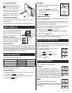
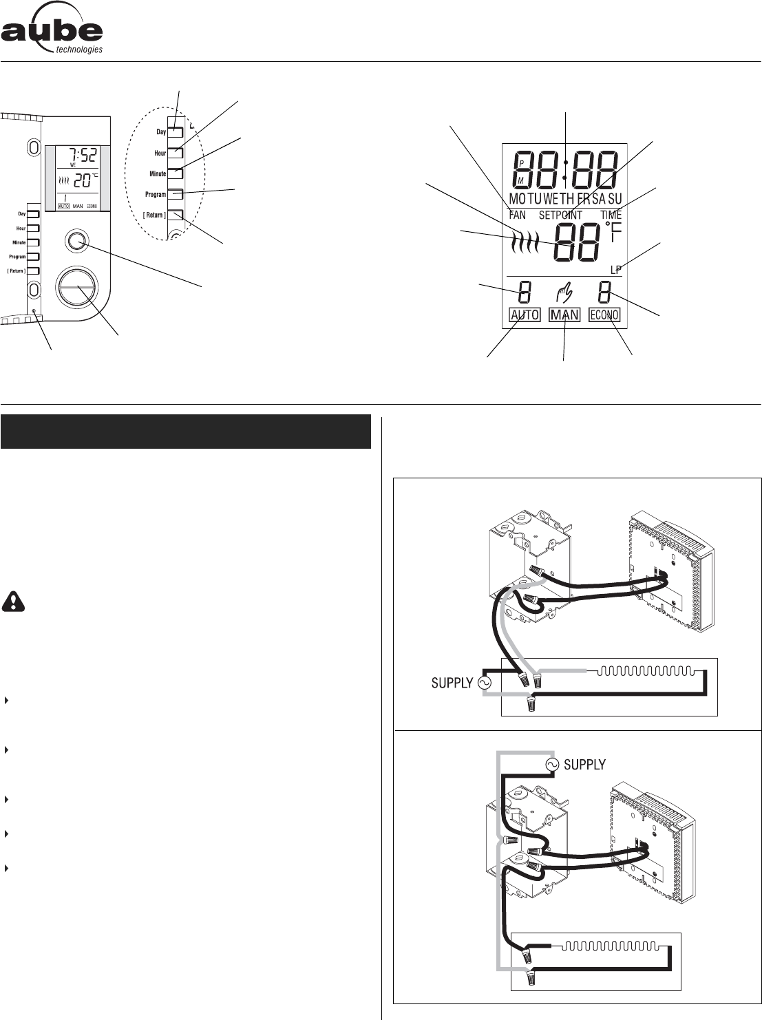
1) Connect the thermostat
Connect the rear wires to the power and load using solderless con-
nectors for copper wires.
INSTALLATION
TH1 04
Installation Instructions and Owner s Guide
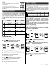
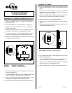
Current program
number when the
Automatic mode
is active
Room
temperature
Heating
indicators
Current time
and day
Manual
mode
Automatic
mode
Econo
mode
Current program
number when
Econo schedule
is active
FAN: displayed when
conventional temperature
control is selected
LP: displayed
during a power
failure
SETPOINT:
displayed when
viewing or
setting the
temperature
TIME: displayed
when time needs
to be adjusted
Temperature
adjustment
buttons
MODE: to select the
desired operating mode
To set the day
To set the
time
To set the
minutes
To access
programming mode
and view programs
To exit a function
RESET:
To reset the
thermostat
4 WIRES
2 WIRES
1/4 400-104-000-A