


VAC
VAC
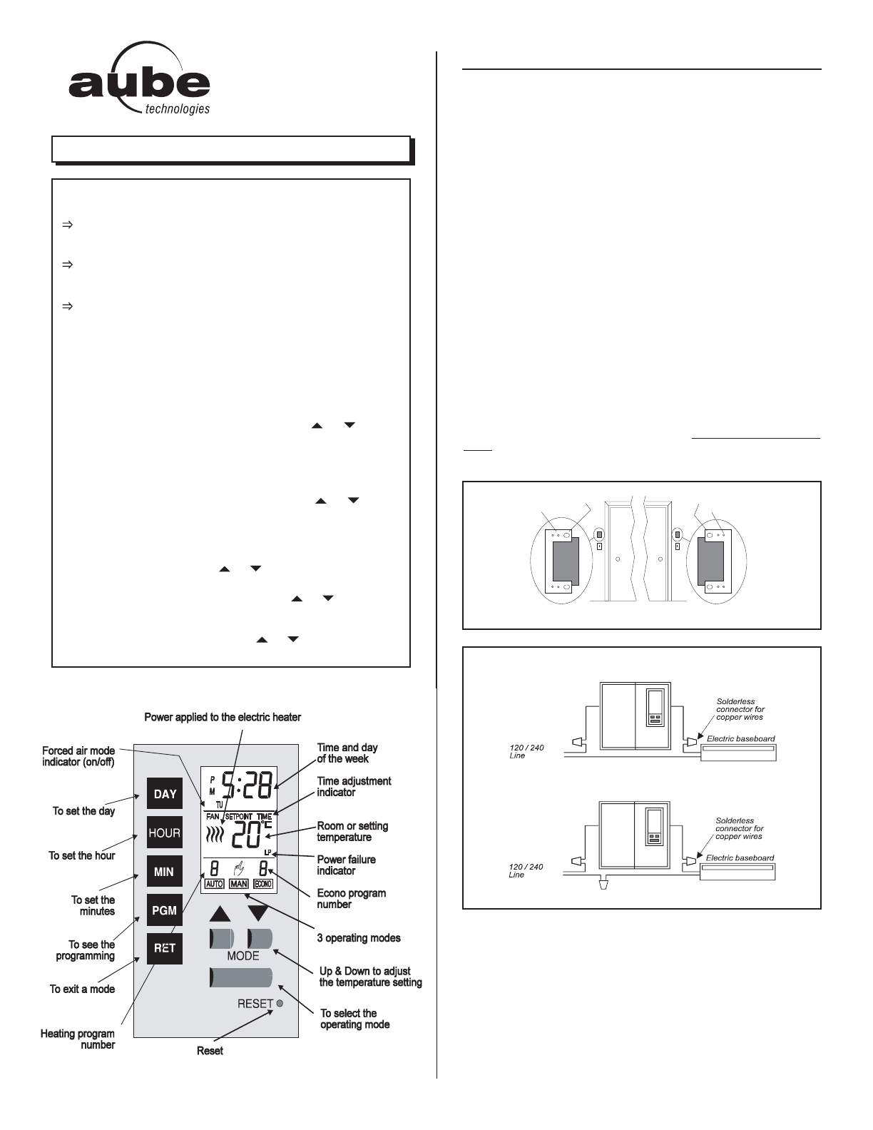
Electrical box 6-32, 1/2"
Thermostat 6-32, 1 1/2"
Left door frame
Right door frame
Electrical box 6-32, 1/2"
Thermostat 6-32, 1 1/2"
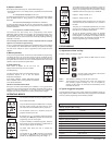
MODEL TH101D
SUMMARY
OPTIONS SELECTION
To change the temperature from °C to °F and back, maintain DAY button
pressed down as RESET button is being pressed on and released. Then
release DAY button.
To change the time format from 24 hours to 12 hours and back, maintain
HOUR button pressed down as RESET button is being pressed on and
released. Then release HOUR button.
To change the heating control from proportional to on/off and back,
maintain MIN button pressed down as RESET button is being pressed on
and released. Then release MIN button.
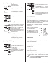
TO SET TIME AND DAY
Press on DAY, HOUR and MIN buttons to adjust time and day.
TO RECORD THE HEATING PROGRAMS
Set the operating mode to AUTO. Use the PGM button to select the
program to be recorded or modified. Once the program is selected,
use HOUR and MIN buttons to set time and or to select
temperature setting.
TO RECORD THE ECONO PROGRAMS
Set the operating mode to ECONO. Use the PGM button to select the
program to be recorded or modified. Once the program is selected,
use DAY, HOUR and MIN buttons to set time and or to select
temperature setting.
OPERATING MODES
To select an operating mode, use MODE button.
AUTO: Runs the program. or shows temperature setting
and can override temporarily your programming.
MAN: Maintain the selected temperature. or change
the temperature setting.
ECONO: Maintain a temperature setting up to the user's pre-
programmed day and time. or shows temperature
setting and can override temporarily your programming.
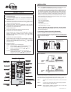
INSTALLATION
1) Connecting wires and mounting thermostat
Secure the wallplate to the electrical box using the 6-32, ½ screws.
Connect the rear thermostat wires to the power supply and to the electric heater
wires using solderless connectors for copper wires (there is no polarity for the
wires). See schematic diagram.
2-wire installation :
u
u
u
u
u
Push the excess wire back into the electrical box to prevent interference with the
thermostat. Secure the thermostat using two (2) 6-32 screws 1 ½ inches long.
Once the thermostat is properly installed, return power to heating system.
Note 1 : All cables and connections must conform to the local electrical
code.
Note 2 : In normal use at full capacity (4000 W), the housing temperature
of the thermostat can reach 35 to 40 °C.
WARNING : Special CO/ALR solderless connectors must be used when
connecting with aluminum conductors.
4-wire installation :
Note : The "Problems and Solutions" section at the end of this user's guide
will help you to correct your problems during the installation.
This thermostat has been designed to operate with any installation which has
a RESISTIVE load not exceeding 4000 W @ 240 VAC or 2000 W @ 120 VAC
such as electric baseboards, radiant ceilings and floors, electric convectors,
etc. It is not compatible with a low voltage controller used by a central heating
system or systems using a contactor or a relay whose current is under 1.0 A.
Electricians or experienced technicians should install the thermostat. This ther-
mostat is designed to be used with a self-protected heating system equipped
with thermal cut off and circuit breaker.
PARTS INCLUDED
• One (1) TH101D thermostat
• Two (2) solderless connectors
• One wallplate
• Two (2) 6-32 screws ½ inch
• Two (2) 6-32 screws, 1 ½ inches
TURN OFF POWER OF THE HEATING SYSTEM AT THE MAIN POWER
P
ANEL TO AVOID ELECTRICAL SHOCK
. Keep air vents of thermostat clean
and free from obstructions.
720-101002-A 1/4