


2
ƽ CRITICAL INSTALLATION WARNINGS
• Install in recreation vehicles only. RV’s are recreation vehicles
designed as temporary living quarters for recreation, camping, or
travel use having their own power or towed by another vehicle.
• All combustion air must be supplied from outside the RV, and all
products of combustion must be vented to outside the RV.
•
DO NOT vent water heater with venting system serving another
appliance.
•
DO NOT vent water heater to an outside enclosed porch area.
• Protect building materials from flue gas exhaust.
• Install water heater on an exterior wall, with access door opening to
outdoors.
•
DO NOT modify water heater in any way.
•
DO NOT alter water heater for a positive grounding system.
•
DO NOT HI-POT water heater unless electronic ignition system
(circuit board) has been disconnected.
•
DO NOT use battery charger to supply power to water heater even
when testing.
USA AND CANADA - FOLLOW ALL APPLICABLE STATE AND LOCAL CODES -
IN THE ABSENCE OF LOCAL CODES OR REGULATIONS, REFER TO CURRENT STANDARDS OF:
• Recreation Vehicles ANSI A119.2/NFPA 501C.
• National Fuel Gas Code ANSI Z223.1 and/or CAN/CGA B149 Installation Codes
• Federal Mobile Home Construction & Safety Standard, Title 24 CFR, part
3280, or when this Standard is not applicable, the Standard for Manufactured
Home Installations (Manufactured Home Sites, Communities and Set-Ups),
ANSI A255.1 and/or CAN/CSA-Z240 MH Series, Mobile Homes.
• National Electrical Code ANSI/NFPA No. 70 and/or CSA C22.1
• Park Trailers A119.5
• CSA standard Z240 RV Series, Recreational Vehicle.
• ASSE Standard 1017 (Mixing Value).
• NSF Standard ANSI/NSF 14-2003 (All Hoses and Plastic Fittings).
GENERAL INSTALLATION
This is a common installation for water heaters. There are other
approved methods such as Flush Mount (MPD 93948) installations.
Consult with your Field Auditor, Account Manager, or the Atwood
Service Department if you have additional questions.
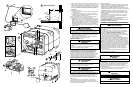
1. Locate water heater on floor of coach before erecting side walls.
The water heater tank must be permanently supported at the same
level as the bottom of sidewall cutout (by the floor or a raised floor)
FIG 2. Provide adequate clearance at rear of unit for service of water
connections.
2. To install water heater on carpeting, you must install appliance on a
metal or wood panel that extends at least three inches beyond the
full width and depth of appliance.
3. If the appliance is installed where connection or tank leakage will
damage adjacent area, install a drain pan (which can be drained to
out side of coach) under water heater.
WIRING
All wiring must comply with applicable electrical codes.
COMBINATION GAS/ELECTRIC MODELS are designed to operate with gas,
electricity, or a combination of both.
• Use electrical metallic tubing, flexible metal conduit, metal clad
cable, or nonmetallic-sheathed cable with grounding conductor. Wire
must have a capacity of 1400 watts or greater. The wiring method
must conform to applicable sections of article 551 of National
Electrical Code ANSI/NFPA 70.
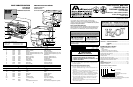
1. Refer to Wiring Diagram (
FIG 12). Make 120 VAC electrical
connections from junction box on back of unit.
a. Connect hot lead to (1) Black.
b. Connect common lead to (2) White.
c. Connect ground wire from electrical service to (3) green ground
lead in junction box 3.
ƽ CAUTION
PRODUCT DAMAGE
• When using Romex
®
with a bare earth ground, take care to position
ground wire so it does not contact the heating element terminals.
• When a cord and plug connection to the power supply are used on
water heater, power cord must be UL listed as suitable for damp
locations, hard or extra hard usage. It must be a flexible cord such
as type S, SO, ST, STO, SJ, SJT, SJTO, HS or HSO cord as described
in National Electrical Code, ANSI/NFPA 70. The length of external
cord to water heater, measured to face of attachment plug, shall be
no less than 2 feet nor more than 6 feet. Supply cord must be a
minimum of 14 AWG and attachment plug must be rated at 15 amps.
ƽ CAUTION
ELECTRICAL DAMAGE
• Label all wires before disconnecting when servicing controls.
• Verify proper operation after servicing.
ELECTRONIC IGNITION
NOTE: It is recommended unit be connected directly to a 12V DC
battery or to filtered side of an AC/DC converter. Avoid connections to
unfiltered side of an AC/DC converter whenever possible. Use a
minimum of 18 gauge wire, UL and CSA listed.
1. Refer to Wiring Diagram (
FIG 12). Install remote switch in a
convenient location. Position wall plate with letters up. Before
making connections turn switch OFF.
2. Install wires see
FIG 10 & 11.
HEAT EXCHANGE MODELS -
FIG 5
1. Push a 5/8˝ diameter coolant system hose (5-A) [with SAE 053 A
Type “E”clamp attached] onto heat exchanger tube (5-B) making a
tight connection.
2. Spread hose clamp and slide toward heat exchange unit past
annular groove (5-C) and release.
3. Continue to HOW TO OPERATE YOUR WATER HEATER and/or Electronic
Ignition OPERATION.
CONTINUE GENERAL INSTALLATION
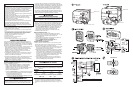
4. Connect both 1/2˝ NPT water lines (
FIG 2) hot water outlet female
and cold water inlet female and 3/8˝ flared LP gas line to the water
heater (
FIG 9).
a. Allow flexibility in water and gas lines so you can pull unit
forward through wall one inch past skin.
b. Seal gas line entrance opening (FIG 9) by sliding grommet (9-B)
onto 3/8˝ tubing (9-D) before flaring tubing (9-E). Pull gas line and
grommet through opening in housing (9-A). Connect flare fitting
(9-C) and press grommet into opening. If gas line tubing is
already flared, cut grommet on one side. Place split grommet
over gas line and press it into opening.
c. Always use pipe lubricant on threads when connecting hot and
cold water couplings. A suitable plastic fitting is recommended.
ƽ CAUTION
PRODUCT DAMAGE
• Do not lift, pull, push or misalign the main burner tube (FIG 3-F).
5. Erect side walls and cut opening. See chart and FIG 1.
Frame with 2x2 lumber (or equivalent).
CUTOUT
(FIG 1 & 2)
CAPACITY CUT OUT DIMENSION DEPTH
Gallon 1-A 1-B 2-C
6 12-5/8˝ 16-1/4˝ 18.5˝
10 15-3/4˝ 16-1/4˝ 21.75˝
MINIMUM CLEARANCE FROM COMBUSTIBLE CONSTRUCTION
Sides: 0˝ Top: 0˝
Back: 0˝ Bottom: 0˝
6. Bend all flanges 90˚ along scored lines (FIG 3-A).
7. To prevent water leaks caulk thoroughly around opening, including
bend slots. Butyl Tape (1-1/3˝x1/8˝) may be substituted for caulking
material.
8. Push unit against caulking, secure 4-corner brackets (
FIG 3-B) to
coach with No. 8 - 3/4˝ round head screws (not furnished) or equivalent.
Complete the installation by inserting the same type of #8 screws in the
holes provided around the flange of the water heater housing. Check all
gaskets, they must adhere to the pan creating an air tight seal.
15
INTENTIONALLY LEFT BLANK