


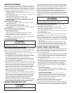

8. Push unit against caulking, secure 4-corner brackets (FIG 3-B) to
coach with No. 8 - 3/4˝ round head screws (not furnished) or equivalent.
Complete the installation by inserting the same type of #8 screws in the
holes provided around the flange of the water heater housing. Check all
gaskets, they must adhere to the pan creating an air tight seal.
9. Attach access door.
a. Snap hinge pin (
FIG 3-C) into clip (FIG 3-D).
b. Slide cover (FIG 3-E) onto hinge pin.
c. Slide hinge pin into cover, snapping into clip at same time (FIG 3-D).
NOTE: To remove hinge pin, support access cover and apply force to
corner of hinge pin.
10. Disconnect unit and its individual shut-off valve from gas supply
line during any pressure testing of system in excess of 1/2 PSIG
(3.4 kPa, 14˝ water column [W.C.]).
DO NOT set inlet pressure higher
than maximum indicated on rating plate of gas valve (13˝ W.C.).
Isolate unit from gas supply line by closing its individual manual
shutoff valve during any pressure testing ≤ 1/2 psig.
ƽ WARNING
FIRE AND/OR EXPLOSION
• DO NOT use matches, candles or other sources of ignition when
checking for gas leaks.
11. Turn on gas and check water heater and all connections for gas
leaks with leak detecting solution.
12. Fill water heater tank, check all connections for water leaks.
PRESSURE-TEMPERATURE RELIEF VALVE
ƽ WARNING
EXPLOSION
• Valve is not serviceable, it must be replaced.
• Tampering with valve will result in scalding injury.
• Tampering with valve will void warranty.
• DO NOT place a valve, plug or reducing coupling on outlet part of
relief valve.
THIS VALVE IS A SAFETY COMPONENT AND MUST NOT BE REMOVED FOR ANY REASON
OTHER THAN REPLACEMENT.
This water heater is equipped with a tempera-
ture and pressure relief valve (FIG 3-G) that complies with standard for
Relief Valves and Automatic Gas Shutoff Devices for Hot Water
Systems, ANSI Z21.22.
If you use a discharge line, do not use a reducing coupling or other
restriction smaller than outlet of relief valve. Allow complete drainage
of both valve and line.
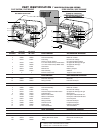
FOR REPLACEMENT PARTS:
•
DO NOT install anything less than a combination temperature-pressure
relief valve certified by a nationally recognized testing laboratory that
maintains periodic inspection of product of listed equipment or materi-
als, as meeting requirements for Relief Valves and Automatic Gas
Shutoff Devices for Hot Water Supply Systems, ANSI Z21.22. Valve
must have a maximum set pressure not to exceed 150 psi.
• Install valve into opening provided and marked for this purpose on
water heater.
• Installation must conform with local codes or in the absence of local
codes, American National Standard for Recreational Vehicles, ANSI
A119.2/NFPA 50IC.
• For an external electrical source, ground this unit in accordance with
National Electrical Code ANSI/NFPA70.
Your ATWOOD PILOT GAS WATER HEATER is now ready for operation.
Continue to HOW TO OPERATE YOUR WATER HEATER
CONSUMER SAFETY WARNINGS
ƽ WARNING
EXPLOSION OR FIRE
• DO NOT store or use gasoline or other flammable vapors and liquids in
the vicinity of this or any other appliance.
• Should overheating occur, or gas supply fail to shut off, turn OFF
manual gas control valve to appliance, or turn gas OFF at the LP
tank. On ELECTRONIC IGNITION MODEL turn operating switch to OFF
position and remove red wire from left hand terminal of ECO switch
or turn gas OFF at the LP tank.
• Use with LP gas only.
• Shut off gas appliances and pilot lights when refueling.
• On PILOT RELIGHT MODELS, turn off the ignition module when refuel-
ing gasoline tanks or LP tanks.
• Turn gas OFF at the LP tank when vehicle is in motion. This disables
all gas appliances and pilot lights. Gas appliances must never be
operated while vehicle is in motion. Unpredictable wind currents
may be created which could cause flame reversal in the burner
tube, which could result in fire damage. The thermal cut off fuse
could also be unnecessarily activated resulting in a complete shut-
down of the water heater requiring replacement of the thermal cut
off. See maintenance of electronic ignition water heaters for further
explanation of the thermal cut off.
• LP tanks must be filled by a qualified gas supplier only.
HOW TO OPERATE YOUR WATER HEATER
ƽ CAUTION
FIRE
• Do not smoke or have any flame near an open faucet.
If water heater has not been used for more than two weeks, hydrogen
gas may form in water line. Under these conditions to reduce the risk
of injury, open hot water faucet for several minutes at kitchen sink
before you use any electrical appliance connected to hot water system.
If hydrogen gas is present, you will probably hear sounds like air
escaping through the pipe as water begins to flow.
ƽ WARNING
SCALDING INJURY
• Do not tamper with pilot orifice.
ƽ CAUTION
PRODUCT FAILURE
• Do not operate without water in tank.
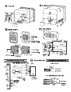
PILOT OPERATION
1. Water heater may be equipped with a White Rodgers
®
or
Robertshaw Unitrol
®
Control
FIG 7.
2. Turn gas control valve knob (
FIG 7-B) to OFF position.
3. Wait at least five minutes to allow accumulated gas in burner com-
partment to escape.
FOR WHITE RODGERS
®
CONTROL (FIG 7)
a. Turn lighting control knob (7-B) to PILOT position and hold
against stop while lighting pilot burner.
b. Allow pilot to burn thirty seconds then release lighting control
knob.
c. Turn lighting control knob (7-B) to ON position.
d. If pilot does not remain lit, repeat operation allowing longer peri-
od before releasing lighting control knob.
e. Set temperature selection lever (7-A) at mark between warm and
hot position.
f. Close access door.
3