5
atlona.com
Toll free: 1-877-536-3976
Local: 1-408-962-0515
EDID (Extended Display Identification Data)
EDID is the exchange of capabilities between a source and display. This handshake ensures the audio and
video signals sent are supported by both source and display.
The switcher has 3 EDID modes: internal picks the highest common audio/video signal between the devices
and the available supported EDIDs within the switcher, external selects the highest common resolution
between the current input and the display, and learned saves the EDID from the current display and locks it
to the output.
When switching between EDID modes the unit will need to be power cycled. To power cycle the power cord
will need to be unplugged and plugged back in.
Internal EDID
The Internally loaded EDID settings are the most common A/V signals that come standard in most TV
displays and computer monitors. The switcher will pick the highest common resolution between the devices.
External EDID
External EDID is the highest common audio/video signal between the current source device and display. It is
useful for devices with uncommon resolutions that are not stored internally. When switching from internal
to external EDID modes, press the EDID button so the external LED illuminates, then power cycle the unit.
When the switcher is turned back on it will sync with the display and determine the EDID.
Learned EDID
Learned EDID allows for a display’s EDID to be saved to the switcher’s nonvolatile memory. To learn the EDID
from the display you first need to be in external EDID mode. Once you’re in external EDID, press and hold
the EDID button until the red copy LED illuminates. Power cycle the switcher and the display’s EDID will be
used.
DC 5V
ETHERNET
S/PDIF
OUT
HDMI OUT
HDMI IN
AT-HD4-V42
RS-232
IR IN
INT
EXT
LEARN EDID
POWER
SOURCE
SELECT
4X2 “HIGH SPEED” HDMI SWITCH
AT-HD4-V42
3D
1
2
3
4
2CH
LPCM 5.1/7.1
BITSTREAM
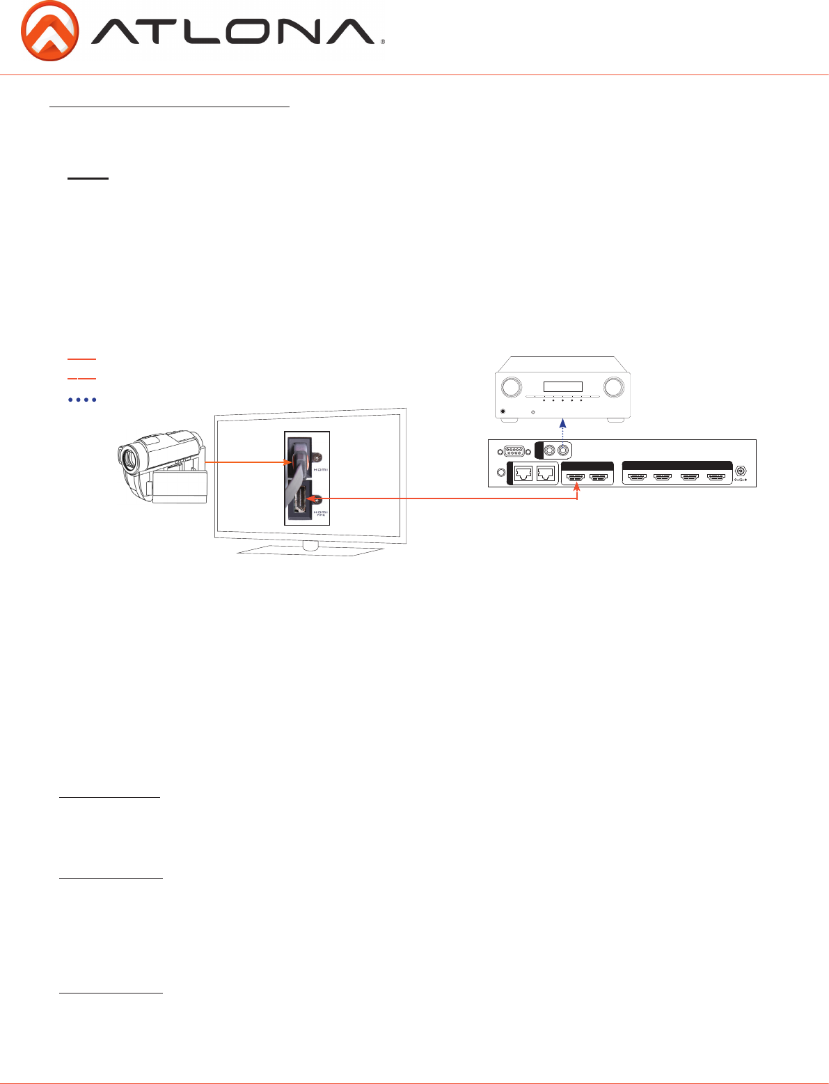
ARC enables a source connected to a display to route audio to an AVR or zone amp.
1. Check to be sure the display supports ARC
2. Enable ARC on the HDMI output of the switcher through RS-232 (command x0AVx1) or by
de-selecting the active input
3. Connect the HDMI output port to the ARC labeled input port on the display
NOTE: The switcher must be connected to the display’s HDMI ARC input
4. Connect the source to a non ARC HDMI input port on the display
5. Connect the S/PDIF port to an AVR or Zone Amp
Audio Return Channel (ARC)
Steps
HDMI
Bidirectional HDMI w/ARC signal
S/PDIF audio loop-out
S/PDIF audio loop-out
Bidirectional HDMI ARC signal
HDMI


