


THEORY
OF OPERATION
This
unit
is a lightweight,
portable
air
cleaner
ernploying
two thermally
protected, high
performance,
flow thrcugh
vacuum
molors
producing
very high
velocity
arrflow
through
the
unit
'By
utilizing
a large
(2
%")
inlet
plus
a variety
of
collectrng
nozzles and
fittings
flne
solid
padiculate
maierial;nd smoke
maY
be
removed
from
the air
by
the
filter media.
An initial
spark trap
collects
large
partioles
before
thev
reach the
filter. An
easy to
emPty
tray
is
attachecl
to the
front cover
to enable
the
removal
of
lhe
larqe
garticles
collected
by
the spark
trap
without
removing
the
filter. This
tap
further
isolates
the
filter
from sparks
in the
case
of a weld,ng
operatlon.
A"cloooed" fllter
liqht.
actuated
by a
d ferential
oress;;
switch
is-an
integral
part
ofthe
unit
When
ihe filters
becote
clogged,
the
light
will
illuminate'
At
this
point,
the filter
should
be
changed
GENERAL
MAINTENANCE
ONLY QUALIFIED
SERVICE
TECHNICIANS
SHOULD
MAKE
REPAIRS
TO
THIS UNIT'
DO NOT
REPLACE
THESE
MOTORS
WITH
MOTORS
OTHER
THAN
THOSE
RECOMMENDED
BY THE
MANUFACTURER,
UNPACKING
Carefully
inspect the
unit
for concealed
damage
that
mav
have occuned
during
shipping
and
handling
lf
ani
damage
is found,
immediately
contact
the
Fr;ioht comoanv.
Make
sure
there
are
no dents
in
the
iousing,
as they
might
prevent
the
filter
from
sliding
into the unit
smoolhly
lf there
is
no
evidence
of da;aqe,
remove the
end
cover
by
releasing
the
two rubGr
latches.
Removal
of
the
front cover
will
allow
inspection
of
the inside
of
the
unit
After
unpacking
the
machine,
check
to
see
that the
following
parts
and
accessories
are
presenl:
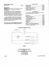
1)
-
10'Flexible
Hose
1)
-
Coupling
1i
-
Flexibbtetal
Hose/Magnetic
Base
comPonent
Parts.
(See
Figlre
#2
For Individual
Parts
Included)
1)
-
Slot
Nozzle
1)
-
Filter
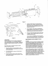
INSTALLATION
(See
Fisure
#1)
1.
lnsert the
filter,
gasketfrrst,
into the
unit. Then
Dlace the rubberthen
steelwashers
over the
threaded
rod. Tighten
the
wing
nut down
so that
the filter
is sealed
and
will not
rotate.
2. Reolace
the front
cover/spark
trap
assembly
and
re-iatch
the cover
using
the
rubber
latches.
3. Connect
the unit
to the
power
source
and
test
the
operation
of
the unit
by
turning
it ON
with the
On/Off switch.
Should
the
motors
not
start, or
should the
machine
make
unusual
noises'
immediatelv
turn
the
machine
off
and
seek
trained
maintenance
personnel.
Once
the
test is
complete,
turn
the unit
back
OFF
4. Attach
the
hose
to the
inlet
5. Assemble
the flexible
metal
hose
and
nozzle
per
Figure
#2.
6 Connect the
hose/nozzle
comolnatlon
assembled
in Step
5 above
to the
machinewith
the
10'flexible
hose
and
the
supplied
coupling
This comDletes
the
basic assembly
ofthe
unit
Deoendinq
upon
the
accessories
ordered
and
the
looistica
oithe
wo*
place,
lhe
installation
oo'nfiguration
maY vary.