Rev. A.3, 5/00 Page- 14
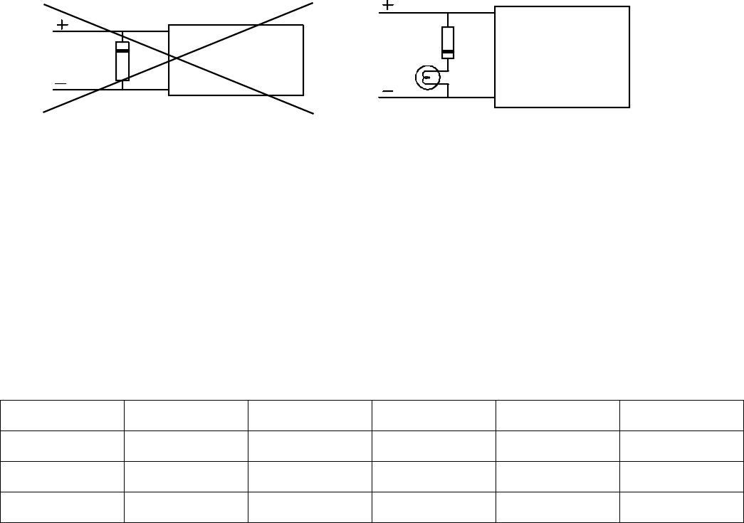
The second problem is when any load is operated in parallel with the Magnalock. A good
example would be adding an incandescent lamp in parallel with the lock so that the lamp
would be illuminated when the lock is powered. The lamp acts like a resistor and allows
current recirculation which will greatly slow lock release time. When you want to add a resistive
load in parallel with the lock, you must put a forward diode in series with the resistive load.
This will block recirculation and restore quick release. Correct practice is shown in Figure 12
below.
A special case exists when you use an
LED connected in parallel with the Magnalock (to
show that the Magnalock is on for example). This does not slow release as the LED does not
allow recirculation but the limited recirculation energy will eventually burn out the LED. LED’s
are susceptible to even a tiny amount of reverse voltage. Therefore add the forward diode as
you would with an incandescent lamp (see Figure 12) to extend the life of the LED.
FIG. 12: WIRING CONSIDERATIONS TO AVOID SLOW RELEASE
MAGNALOCK
RED
BLACK
NEVER CONNECT PARALLEL
REVERSE DIODE AS SHOWN
MAGNALOCK
RED
BLACK
USE A FORWARD DIODE WITH ANY PARALLEL
RESISTIVE LOAD SUCH AS A LAMP
3.4 WIRE GAUGE SIZING
If the power supply is distant from the lock, voltage will be lost (dropped) in the connecting
wires so that the Magnalock will not receive full voltage. The following chart shows the
minimum wire gauge that will hold voltage drop to an acceptable 5% for different lock to
power supply distances. Proper use of the chart assumes a dedicated pair of wires to
power each Magnalock (no common negative). Note that a Magnalock operating on 24 volts is
a much better choice for long wire runs as it has 4 times the resistance of a 12 volt installation.
Also note that the correct calculation of wire sizing is a very important issue as the installer is
responsible to insure that adequate voltage is supplied to any load. In multiple device
installations, the calculation can become quite complex so
refer to Appendix B for a more
complete discussion.
Distance Gauge 12V Gauge 24V Distance Gauge 12V Gauge 24V
80 FT 20 GA 24 GA 800 FT 10 GA 16 GA
200 FT 17 GA 22 GA 1500 FT. 8 GA 14 GA
400 FT 14 GA 20 GA 3000 FT N/A 12 GA
3.5 SENSTAT MAGNALOCKS: “SC”
Securitron's optional patented Senstat feature provides true lock status sensing. In many
electrically controlled door security systems, status sensing is provided by a magnetic switch
on the door itself. This indicates the door is closed but not necessarily secured. Securitron's
Senstat monitors the lock rather than the door and therefore provides higher security (but note
that it can’t be used as an auto-relock input to an access control system).
An “SC” Magnalock provides a dry SPDT output which changes state when the lock is reporting
secure
(1 Amp @ 30 VDC maximum). This is accomplished by conducting the input power of
the lock through the strike and employing it to energize an internal SPDT relay. The white wire
is the Senstat relay common. Green is closed to white when the lock is secure and Orange is
closed to white when the lock is not secure.


