


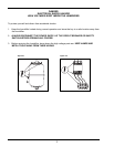
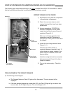

c. Use the template provided to cut installation
holes in the duct for the dispersion tube
as in Figure 7-2 (and optional drain tube,
Figure 7-3).
d. Insert the dispersion tube into the duct so
the holes face upward. Fasten the mounting
plate to the outside of the duct with sheet
metal screws. If the dispersion tube is 36"
long or more, support the far end with
threaded rod or similar means.
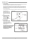
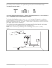
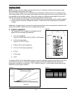
e. Connect the dispersion tube to the steam generator using 1¼" (EHU-701) or 1½" (EHU-703,704)
nom. size hard copper tube (customer supplied) and the two short hoses supplied with the
humidifier (Figure 8-1). Pipe size may
need to be increased to 1½" or 2"
when piping runs are long or back
pressure in duct is high, see Figure 9-2.
If piping plus duct back pressure
exceeds 4" WC, please consult factory.
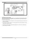
In addition, a short length of nominal
1½" threaded black iron pipe
and a copper tube to female pipe
thread adaptor must be supplied
by the customer for attaching the
piping to 703 or 704 tanks (Figure 8-2).
A 1½" to 1¼" reducer will be required
to connect the dispersion tube to the steam pipe of Models EHU-703/704 (Figure 8-5).
The steam pipe must be free of kinks and sags to allow for gravity drainage of condensate.
(Provide pitch of 1" per foot towards the unit.) Pipe supports may be required to accomplish
this. Insulate the copper tube to minimize condensation.
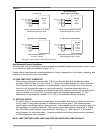
The preferred installation of the
dispersion tube is above the
humidifier with a maximum piping
run of 20 feet or less (Figure 8-3).
Figure 8-4 shows the correct
installation when:
1) You cannot achieve a 1" per
foot reverse slope of the piping.
2) Piping runs range from 20 to the
maximum of 40 feet of equivalent run.
3) Elbows or vertical risers must be
placed in the piping.
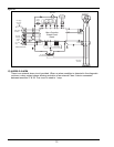
4) The steam dispersion tube MUST BE
below the humidifier. For this installation
use a 1¼" copper tee for the drain
connection of an EHU-701 or a 1½"
copper tee for EHU-703 or 704
(Figure 8-5).
8
1-1/2" Copper Tube
Copper Tube
Female Pipe Adapt
er
1-1/2" Pipe
Hose Clamp
2" I.D. Hose
S
team
Outlet
EHU-701
Floor
Drain
6" Water Seal
Duct Above Outlet
Holes in dispersio
n
tube to be installe
d
in "UP" position
1-1/2" to 1-1/4" Copper
R
educer if Needed
1-1/2" I.D. Hose
1/2" PVC
Tubing
1/2" O.D.
Copper Tubing
1-1/4" Copper Tube
1-1/2" I.D. Hose
EHU-701
Steam Generator To
p
Figure 8-1. EHU 701
Figure 8-2. EHU 703/704
Figure 8-3
Figure 8-4
Figure 8-5