11
connected. If unvented hot water storage systems are installed
where discharges from saf
ety devices may not be apparent i.e. in
dwellings occupied by the blind, infirm or disabled people,
consideration should be given to the installation of an
electronically operated device to warn when discharge takes
place
. Note: The discharge will consist of scalding water and
steam. Asphalt, roofing felt and non-metallic rainwater goods may
5
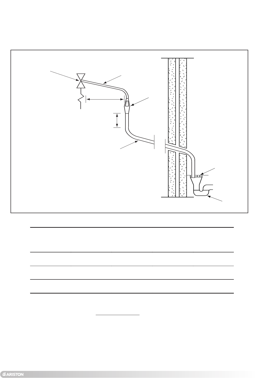
00mm Max.
300mm
Min.
Temperature & pressure
relief valve
Metal discharge pipe (D1) from
temperature & pressure relief valve.
to tundish.
Metal discharge pipe (D2) from tundish
with continuous fall. See Table 2 and worked
example.
Tundish
Fixed grating
Trapped gulley
Discharge below
fixed grating.
(see page 10 for
alternative points
of discharge).
Valve outlet size Minimum size of
discharge pipe D1*
Minimum size of
discharge pipe D2*
from tundish
Maximum
resistance allowed,
expressed as a
length of pipe (i.e.
no elbow or bends)
Resistance created
by each elbow or
bend
G 1/2 15mm 22mm
28mm
35mm
Up to 9m
Up to 18m
Up to 27m
0.8m
1.0m
1.4m
G 3/4 22mm 28mm
35mm
42mm
Up to 9m
Up to 18m
Up to 27m
1.0m
1.4m
1.7m
G 1 28mm 35mm
42mm
54mm
Up to 9m
Up to 18m
Up to 27m
1.4m
1.7m
2.3m
TABLE 2. Sizing of copper discharge pipe “D2” for common temperature valve outlet sizes.
be damaged b
y such discharges
.
WORKED EXAMPLE
The e
xample below is for a G
1
/
2
temper
ature & pressure relief valve with a
discharge pipe (D2) having 4 no. elbows and length of 7m from the tundish to
the point of discharge.
F
rom
TABLE 2;
Maximum resistance allowed for a straight length of 22mm copper discharge
pipe (D2) from G
1
/
2
temperature & pressure valve is 9m. Subtract the resistance
for 4 no. 22mm elbows at 0.8m each = 3.2m. Therefore the maximum permitted
length equates to: 5.8m. As 5.8m is less than the actual length of 7m therefore
FIG. 2.9
www.tradeplumbing.co.uk Call Sales On 08708034288
www.tradeplumbing.co.uk Call Sales On 08708034288


