17
installation
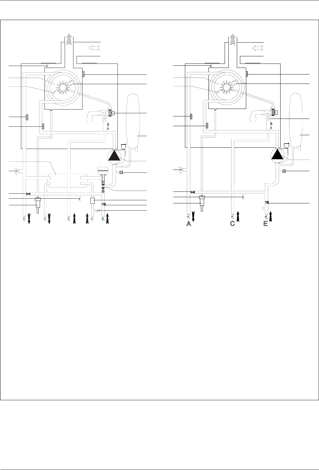
1. Manual air vent
3. Burner
4. Detection electrode
5. C.H. ow temperature probe
6. C.H. return temperature probe
7. Secondary heat exchanger
8. C.H. pressure relief valve
10. By-pass
11. Drain valve
12. Condensate trap
13. Filling loop
14. C.H. circuit lter
15. D.H.W. Flow switch
16. diverter valve
17. water pressure sensor
18. circulation Pump
19. expansion vessel
20. modulating Fan
21. ignition electrodes
22. thermal fuse
Water circuit diagram
1
4
3
11
8
10
12
14
17
18
19
20
21
22
6
5
A C E
1
4
3
11
8
10
12
13
14
15
16
17
18
19
20
21
22
7
6
5
A
A
B
B
C
C
D
D
E
E


