19
B023
3.4 Initial Start-up
The checks to be run before initial start-up are as follows:
1. Make sure that:
-the screw on the automatic air valve has been loosened when the
system is full;
- If the water pressure in the system is below 1 bar, bring it up to the appro-
priate level;
-Check to see whether the gas cock is closed;
-Make sure that the electrical connection has been made properly and that
the earth wire is connected to an efficient earthing system;
- Supply power to the boiler by pressing the On/Off switch <L> - the L.E.D. “I”
will turn on - turn the selector knob “C” to the <
winter>
setting. This will start
the circulation pump. After 7 seconds, the boiler will signal a shut-
down due to failure ignition. Leave the boiler as it is until all of the air has
been bled from the lines.
-Loosen the cap on the head of the pump to eliminate any air pockets;
-Repeat the procedure for bleeding the radiators of air;
-Open the taps for a brief period;
-Check the system pressure and, if it has dropped, open the filling-loop
again to bring the pressure back up to 1 bar.
2. Check the exhaust flue for the fumes produced by combustion.
3. Make sure that all gate valves are open;
4. Turn on the gas cock and check the seals on the connections, including the
one for the burner, making sure that the meter does not signal the passage
of gas. Check the connections with a soap solution and eliminate any leaks.
5. Press the reset button “A” for the lighting system; the spark will light the
main burner. If the burner does not light the first time, repeat the procedure.
6. Check the minimum and maximum pressure values for the gas going to the
burner; adjust it if needed using the values indicated in the table in
section 4.
(See the relative section for burner pressure adjustment within the servicing
manual).
3.5 Operational
Adjustments
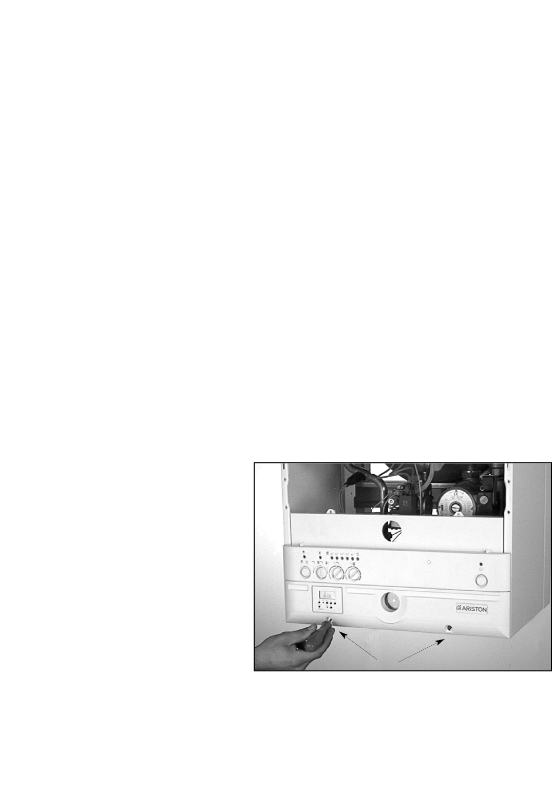
The boiler was designed to make it easy to regulate and check the various
features. To access the areas where the adjustment and control devices are
located, simply remove the plugs by pressing from the inside, unscrew the
screws “A” and remove the bottom part of the instrument panel, rotating it
upward.
Right hand side service panel also provides access to:
- the power supply cord connector;
- the fuses.
Left hand side:
- the potentiometer for regulating the ignition delay (anti-cycling) feature, which
can be set from 0 to 2 minutes (factory set at 1 minute);
- the potentiometer for regulating the soft-light feature, the setting for which
can range from the minimum thermal power to the maximum:


