


4 - 12
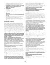
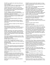
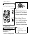
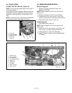
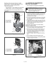
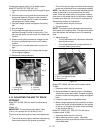
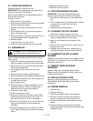
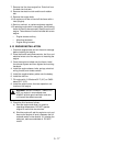
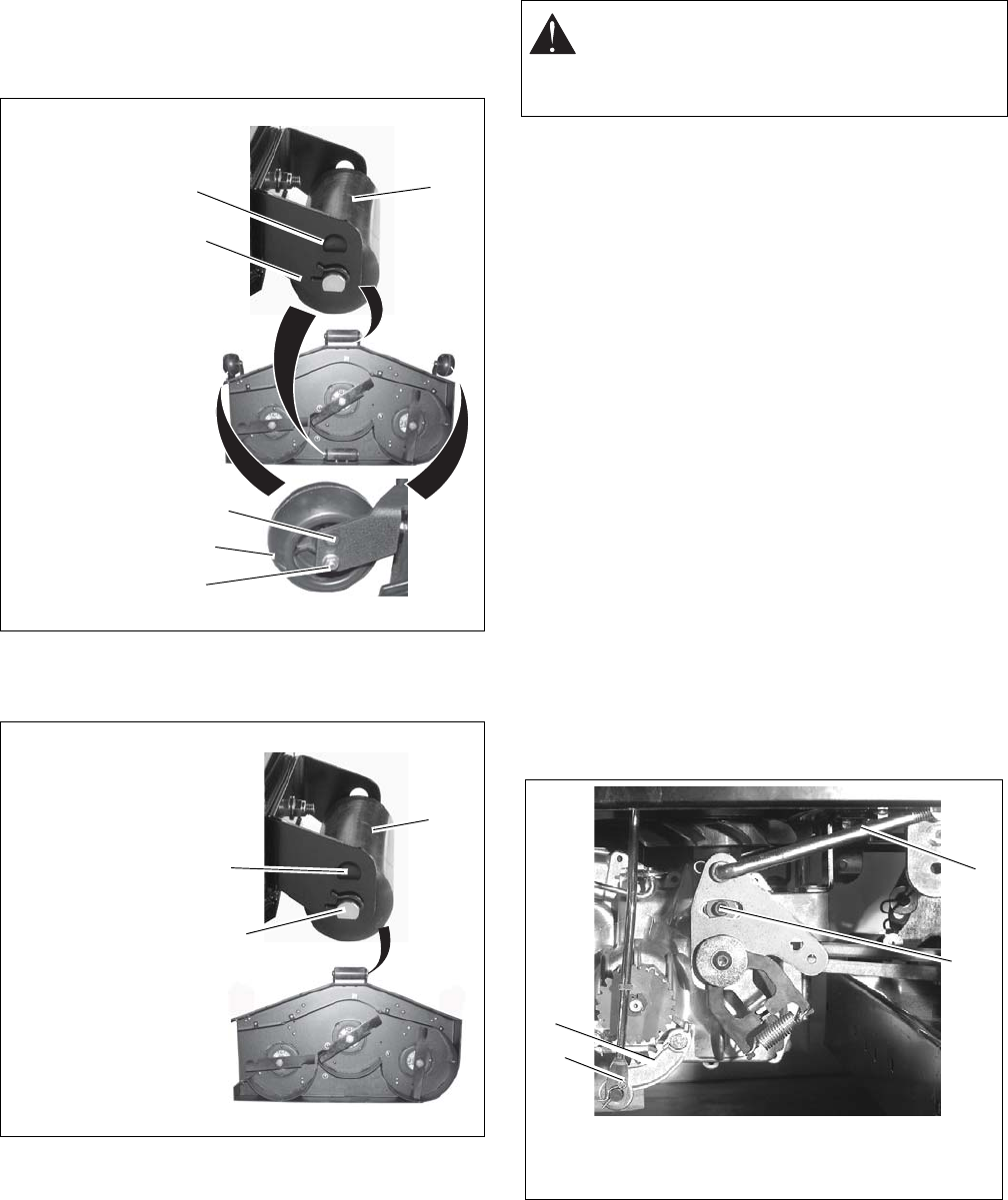
See Figure 9 for anti-scalp locations on models
915067, 055, 057, 059, 501. See Figure 10 for anti-
scalp locations on model 915065 and 502.
There are two positions:
• Highest Position: Use to disable anti-scalp feature.
• Lowest Position: Use for all cutting positions.
In the lowest position the anti-scalp rollers will touch
the ground.
Figure 9
Figure 10
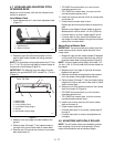
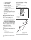
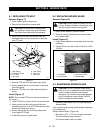
4.9 HYDROSTATIC TRANSMISSION
NEUTRAL ADJUSTMENT
1. Shut off engine and engage the parking brake.
2. Position rear wheels off the ground. Be careful to
secure the unit to the lift or position the unit to face
a wall for safety. Disconnect the rods from the
handlebars to the linkage.
3. Pull the pin that holds the locking arm to the brake
rod then release the locking arm and disengage it
from the gear.
4. Engage seat switch and start the engine.The drive
wheels should not be rotating. If the wheels are not
driven to rotate, proceed to Steering Control
Neutral Adjustment.
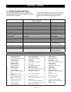
To adjust the neutral setting for no wheel rotation
Model EZT 915065 and 502:
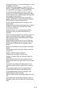
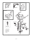
5. Use a hex wrench to loosen the locking bolt (Figure
11) until the linkage can be rotated by hand.
6. With the engine running and the drive wheels off
the ground, rotate the linkage in either direction.
The correct linkage position is when the wheel is
not being driven (under power).
7. Hold the linkage in place and tighten the locking
bolt.
8. Shut off engine and reconnect steering rods.
9. Reconnect parking brake pin. Check parking brake
linkage for proper movement.
Figure 11
1
3
2
3
1
2
1. Anti-scalp Roller
2. Lowest Position
3. Highest Position
OE0038
1. Anti-scalp Roller
2. Lowest Position
3. Highest Position
1
3
2
OE0310
CAUTION: PREVENT personal injury!
ALWAYS MAKE CERTAIN that jack(s) or
blocks used are stable, strong and will
support the weight of the unit.
1. Locking Bolt
2. Steering Rod
3. Pin
4. Locking Arm
1
2
3
4