


INSTALLATION INSTRUCTIONS
LOCATION
To ensure proper operation, the thermostat should be
mounted on an inside wall in a frequently occupied
area of the building. In addition, its position must be
at least 18" (46cm) from any outside wall, and approx-
imately 5' (1.5m) above the floor in a location with
freely circulating air of an average temperature.
BE SURE TO AVOID THE FOLLOWING LOCATIONS:
- behind doors or in corners where freely circulating
air is unavailable
- where direct sunlight or radiant heat from appli-
ances might affect control operation
- on an outside wall
- adjacent to, or in line with, conditioned air dis-
charge grilles, stairwells, or outside doors
- where its operation may be affected by steam or
water pipes or warm air stacks in an adjacent parti-
tion space, or by an unheated/uncooled area
behind the thermostat
- where its operation will be affected by the supply
air of an adjacent unit
- near sources of electrical interference such as arc-
ing relay contacts
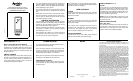
THERMOSTAT INSTALLATION
1. Insert a flat blade screwdriver or coin 1/8" into the
slot located in the bottom center of the thermostat
case and twist 1/4 turn. When you feel or hear a click,
grasp the case from the bottom two corners and sep-
arate from the subbase as shown in the diagram at
the right. Some models require more force than oth-
ers when separating due to the number of terminals
on the subbase.
2. Swing the thermostat out from the bottom.
3. Lift the thermostat up and off the subbase.
4. Place the rectangular opening in the subbase over the
equipment control wires protruding from the wall and,
using the subbase as a template, mark the location of
the two mounting holes (exact vertical mounting is
necessary only for appearance).
5. Use the supplied anchors and screws for mounting on
drywall or plaster; drill two 3/16" (5mm) diameter
holes at the marked locations; use a hammer to tap
the nylon anchors in flush to the wall surface and fas-
ten subbase using the supplied screws. (Do not over-
tighten!)
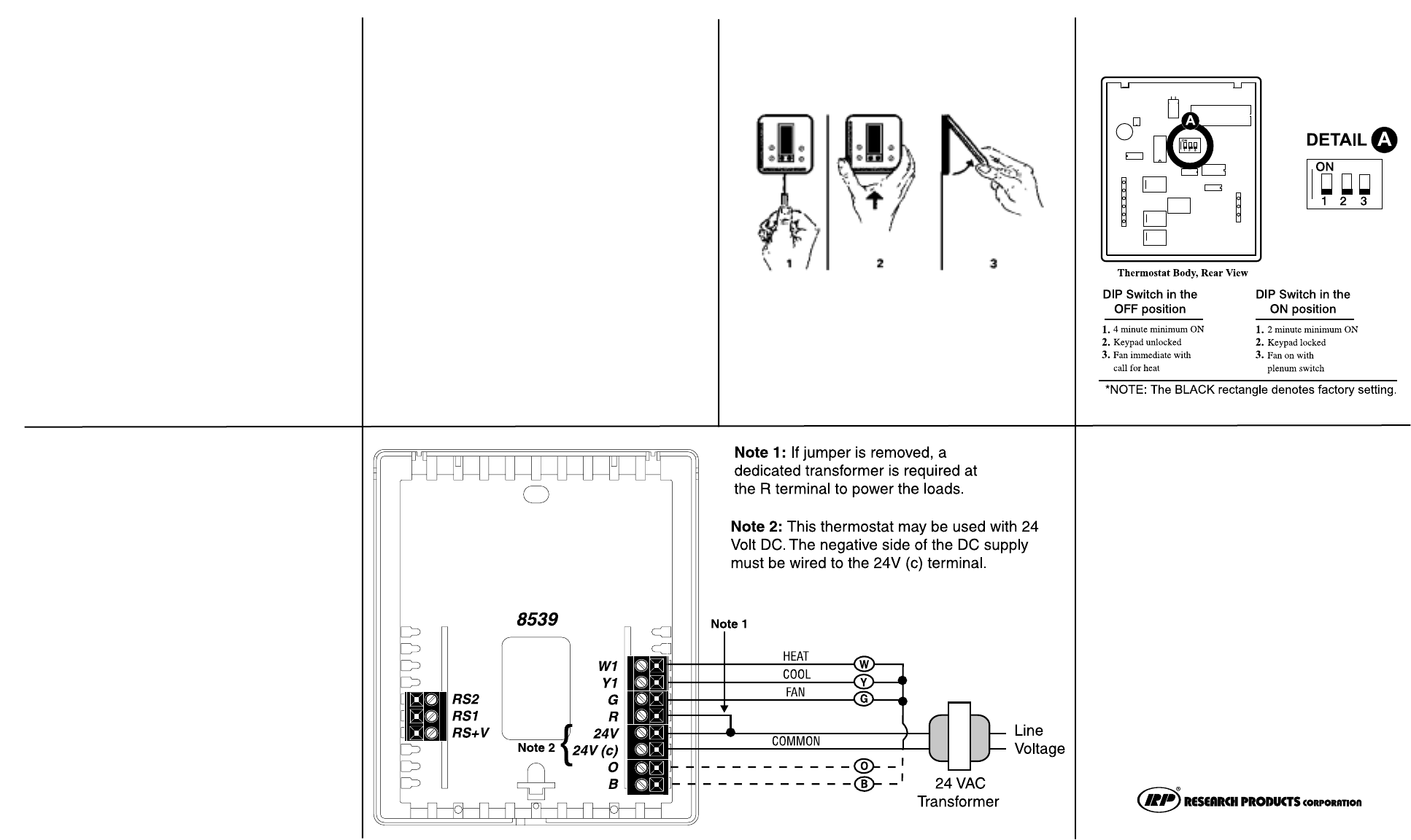
6. Connect the wires from your system to the thermostat
terminals as shown in the wiring diagrams. Carefully
dress the wires so that any excess is pushed back
into the wall cavity or junction box. Ensure that the
wires are flush to the plastic subbase. The access
hole should be sealed or stuffed to prevent drafts
from affecting the thermostat.
7. Before the thermostat is reinstalled on the subbase,
install the optional indoor remote sensor (model
8002), if used. Refer to the installation instructions
supplied with the model 8002.
REPLACING THE THERMOSTAT
ON THE SUBBASE
1. Position the thermostat on the hinged tabs located at
the top of the subbase.
2. Gently swing the thermostat down and press on the
bottom center edge until it snaps in place.
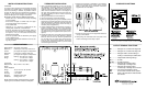
SLIDE SWITCH SETTINGS
SPECIFICATIONS
Rated Voltage 20-30 VAC, 24 nominal
Rated A.C. 0.05 Amps to 0.75 Amps continuous
Current per output with surges to 3 Amps Max.
Rated D.C. 0 Amps to 0.75 Amps continuous
Current per output with surges to 3 Amps Max.
Control Heating: 38° to 88°F in 1° Steps
Range 5° to 30°C in 1° Steps
Cooling: 60° to 108°F in 1° Steps
16° to 40°C in 1° Steps
Thermostat
Measurement 28° to 124°F or 0° to 48°C
Range
O.D.T. Displayed
Range -50° to 124°F or -48° to 48°C
Control ± .5°C at 20°C
Accuracy ± 1°F at 68°F
Minimum (between heating and
Deadband cooling) 2°F or 1°C
NOTE: This thermostat contains electronic circuitry
replacing the conventional mechanical anticipator.
OUTPUT TERMINAL FUNCTIONS
W1. . . . . . . . Energizes on a call for first stage heat
Y1 . . . . . . . . Energizes on a call for first stage cool
G . . . . . . . . . Energizes with a call for heating or
cooling or selected by the FAN button
R . . . . . . . . . Independent switching voltage
24 V. . . . . . . 24 VAC
24 V(c). . . . . 24 VAC (common)
O . . . . . . . . . Energizes the reversing valve
continuously in cooling mode
B . . . . . . . . . Energizes the reversing valve
continuously in heating and off modes
RS2 . . . . . . .For outdoor temperature sensor
RS1 and/or indoor remote sensor options.
RS+V Refer to the instructions included with
the sensors.
P.O. BOX 1467 • MADISON, WI 53701-1467
CALL 608/257-8801 • FAX 608/257-4357
Products For Better Indoor Air Quality.