


Multiple Support Module Installation
up to 4 support modules can be connected to provide
temperature averaging in a large area or for several zones being
controlled by the same system. The maximum cumulative
distance between the support modules and the thermostat is
1000 ft.
2.
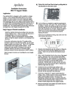
CAUTION: Make sure that there is no power to the
support modules by removing the thermostat from the
subbase.
Wire the first support module using the single support
module instructions. Daisy chain the remaining support
modules as shown below.
THERMO- MODULE MODULE MODULE MODULE
STAT 1 2 3 4
RSR - RSR - RSR - RSR - RSR
RSC - RSC - RSC - RSC - RSC
RSB - RSB - RSB - RSB - RSB
RSA - RSA - RSA - RSA - RSA
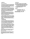
3. Set dte TT Support Module dipswitches.
OFF
ADDRESS
ADDRESS
MONITOR (SI)
MONITOR (S2)
SPARE
TI/T2 (SI)
ADDRESS
ADDRESS
CONTROL (SI)
CONTROL (S2)
SPARE
ON BOARD SENSOR
Dipswitch 3 - Temperature Sensor 1
Each support module has two sensors, Sensor I and Sensor 2.
Determine whether you want the Sensor I input to monitor or
control temperature. If dipswitch number 3 is in the "off'
position, it will monitor the temperature. If the support
module is set to Address 1 and the Sensor 1 input is set to
"monitor", then the monitored temperature will be
displayed as the remote temperature in the lower left hand
corner of the thermostat. Otherwise, the monitored value
will only be available through the software that supports this
specific function.
If dipswitch 3 is set to the "on" position, it will use the reported
temperature to control the thermostat. The sensor control
temperature will be displayed on the thermostat. If multiple
support modules are daisy chained together, all of the sensors
set to control will be averaged and the average temperature will
be displayed on the thermostat.
Dinswitch 4 - Temperature Sensor 2
Determine whether you want the Sensor 2 input to monitor or
control temperature. If dipswitch number 4 is in the "off"
position, it will monitor the temperature.
If dipswitch 4 is set to the "on" position, it will use the reported
temperature to control the thermostat. The sensor control
temperature will be displayed on the thermostat. If multiple
support modules are daisy chained together, all of the sensors
set to control will be averaged and the average temperature will
be displayed on the thermostat.
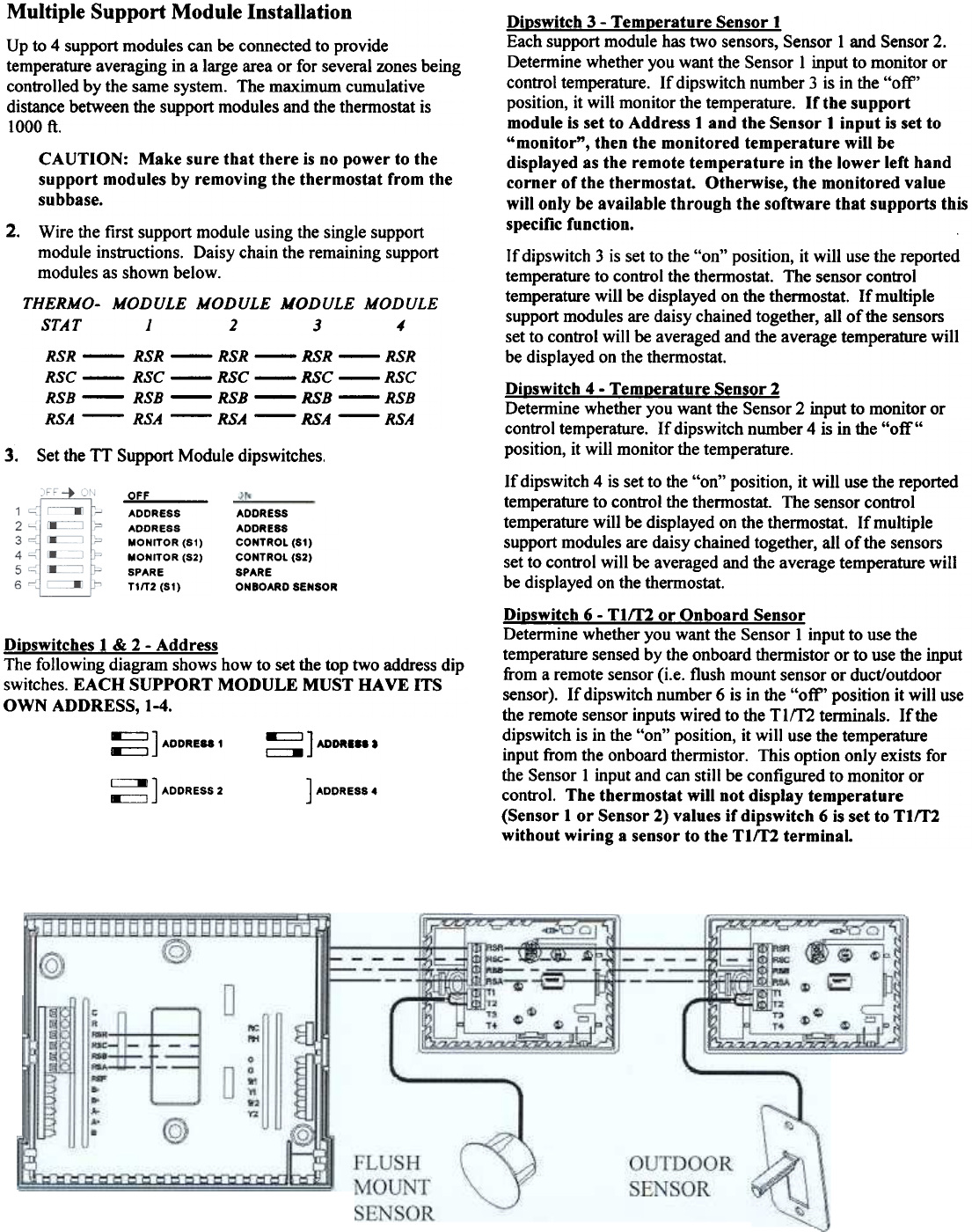
Dioswitch 6 - TIff2 or Onboard Sensor
Determine whether you want the Sensor 1 input to use the
temperature sensed by the onboard thermistor or to use the input
from a remote sensor (i.e. flush mount sensor or duct/outdoor
sensor). If dipswitch number 6 is in the "off' position it will use
the remote sensor inputs wired to the TIm terminals. If the
dipswitch is in the "on" position, it will use the temperature
input from the onboard thermistor. This option only exists for
the Sensor 1 input and can still be configured to monitor or
control. The thermostat will not display temperature
(Sensor 1 or Sensor 2) values if dipswitch 6 is set to TIff2
without wiring a sensor to the TIm terminal.
Dioswitches 1 & 2 - Address
The following diagram shows how to set the top two address dip
switches. EACH SUPPORT MODULE MUST HAVE ITS
OWN ADDRESS, 1-4.
~ ] ADDRE88 1
~] MORISS.
~ ] ADDRESS 2
] ADDRESS 4