


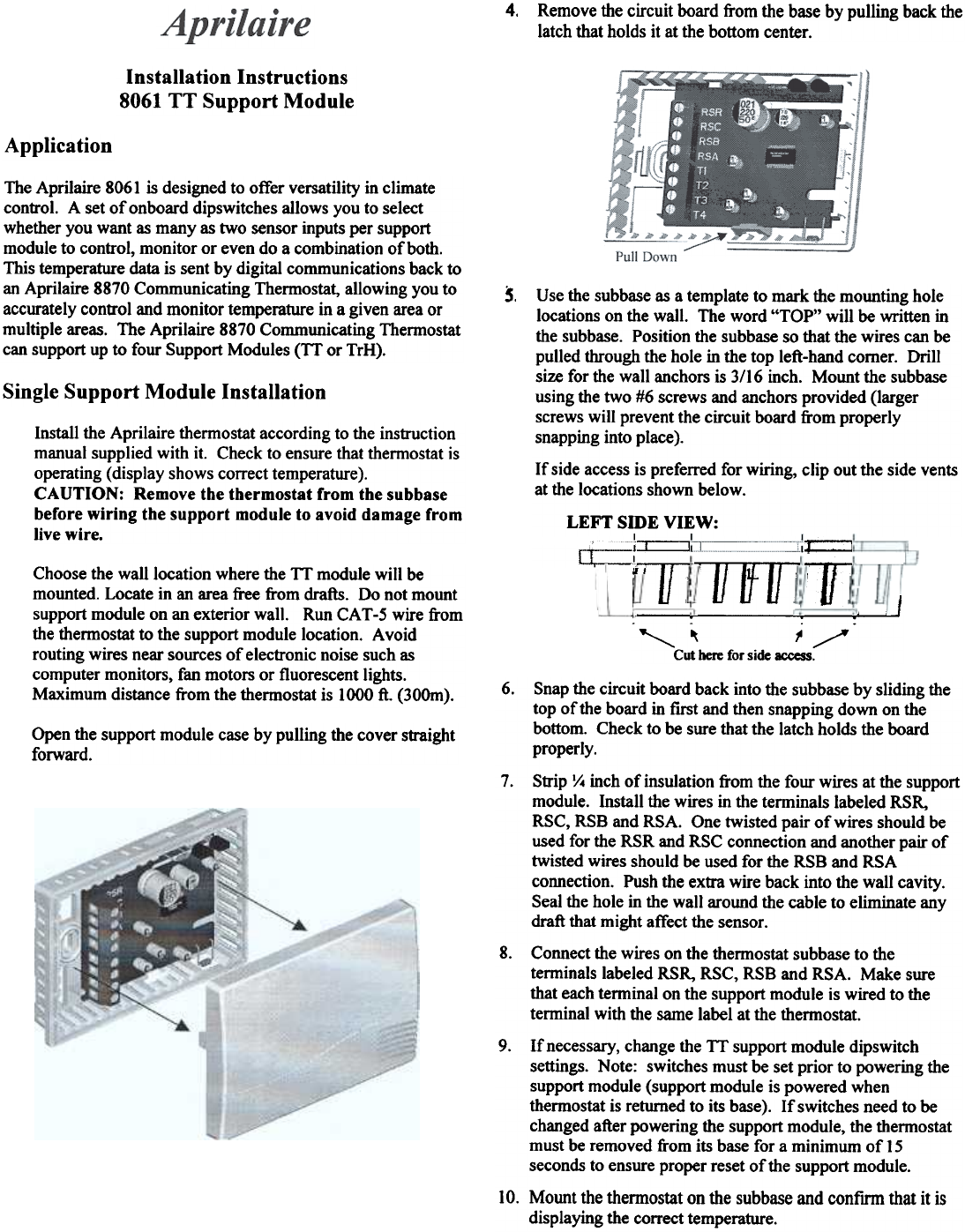
4. Remove the circuit board from the base by pulling back the
latch that holds it at the bottom center.
Installation Instructions
8061 TT Support Module
Application
The Aprilaire 8061 is designed to offer versatility in climate
control. A set of onboard dipswitches allows you to select
whether you want as many as two sensor inputs per support
module to control, monitor or even do a combination of both.
This temperature data is sent by digital communications back to
an Aprilaire 8870 Communicating Thermostat, allowing you to
accurately control and monitor temperature in a given area or
multiple areas. The Aprilaire 8870 Communicating Thermostat
can support up to four Support Modules (Tf or TrH).
5.
Single Support Module Installation
Use the subbase as a template to mark the mounting hole
locations on the wall. The word "TOP" will be written in
the subbase. Position the subbase so that the wires can be
pulled through the hole in the top left-hand comer. Drill
size for the wall anchors is 3/16 inch. Mount the subbase
using the two #6 screws and anchors provided (larger
screws will prevent the circuit board from properly
snapping into place).
If side access is preferred for wiring, clip out the side vents
at the locations shown below.
LEFT SmE VIEW:
I I I
~
-T
Install the Aprilaire thermostat according to the instruction
manual supplied with it. Check to ensure that thermostat is
operating (display shows correct temperature).
CAUTION: Remove the thermostat from the subbase
before wiring the support module to avoid damage from
live wire.
~
~
If] I
Choose the wall location where the 1T module will be
mounted. Locate in an area free from drafts. Do not mount
support module on an exterior wall. Run CAT -5 wire from
the thermostat to the support module location. A void
routing wires near sources of electronic noise such as
computer monitors, fan motors or fluorescent lights.
Maximum distance from the thermostat is 1000 ft. (300m).
T1Jff I
.. ..
,,~ ~/
Cut here for side access.
OpeD the support module case by pulling the cover straight
forward.
6. Snap the circuit board back into the subbase by sliding the
top of the board in first and then snapping down on the
bottom. Check to be sure that the latch holds the board
properly.
7. Strip y. inch of insulation from the four wires at the support
module. Install the wires in the terminals labeled RSR,
RSC, RSB and RSA. One twisted pair of wires should be
used for the RSR and RSC connection and another pair of
twisted wires should be used for the RSB and RSA
connection. Push the extra wire back into the wall cavity.
Seal the hole in the wall around the cable to eliminate any
draft that might affect the sensor.
8. Connect the wires on the thermostat subbase to the
terminals labeled RSR, RSC, RSB and RSA. Make sure
that each terminal on the support module is wired to the
terminal with the same label at the thermostat.
9. If necessary, change the Tf support module dipswitch
settings. Note: switches must be set prior to powering the
support module (support module is powered when
thermostat is returned to its base). If switches need to be
changed after powering the support module, the thermostat
must be removed from its base for a minimum of 15
seconds to ensure proper reset of the support module.
10. Mount the themostat on the subbase and confirm that it is
displaying the correct temperature.