


READ COMPLETE SAFETY INSTRUCTIONS AND INSTALLATION TEMPLATE BEFO RE STARTIN G I NSTALLATION
TEM PLATE MUST BE LEVEL
– TOP –
READ REVERSE SIDE FIRST! READ REVERSE SIDE FIRST!
IMPORTANT! Be sure owner’s manual containing instructions for
operation and warranty information is given to owner in order to avoid
unnecessary calls. Warranty is voidunless humidifier is installed by qualified
heatingandair conditioningcontractor due topossible misapplicationofproduct.
NOTE: BEFORE LEAVING THE
JOB SITE, MAKE SURE:
1. Saddle valve is fully open.
2. All plumbing connections are
watertight.
3. Humidifier functions properly.
4. Bypass damper is in proper
position.
Figure 1 Figure 2 Figure 3
10008974 B2205116A 4.10
90-1067 90-1068 90-1069
12
10
2
7
9
6
11
1
4
3
5
8
90-1250
FURNISHED ITEMS
ITEMS NOT FURNISHED
B
uilt-inbypassdamper
2
4VACTransformer
DigitalHumidifierControl(Model500only)
ManualHumidifierControl(Model500Monly)
HumidifierControlInstallationInstructions
Saddlevalve
H
umidifierInstallationTemplate
Mountingscrews(sheetmetalscrews)
Watersupplyline(
1
⁄4”copper)
Drainline(
1
⁄2”I.D.hose)
Lowvoltagewire
B
ypassductwork
M
odel50CurrentSensingRelay(ifrequired)
1. Front Cover
2. Base
3. Feed Tube
4. Water Distribution Tray
5. Water Panel Evaporator
6. Scale Control Insert
7. Integral Damper
8. Damper Handle
9. Drain Spud
10. Hole Plug
11. Nameplate
12. Solenoid Valve
PARTS LIST
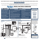
1. Press top & bottom tabs to remove
cover (1). Pull feed tube (3) out of
distribution tray (4).Remove Water Panel
®
Evaporator assembly. See Figure 1.
2. Humidifier is supplied with bypass
duct connection on left. For right side
bypass, swap location of drain spud (9)
and cap (10). Twist to remove spud
and cap.
3. Position template on supply or return
plenum. Make sure template is level.
Allow clearance for drain line and for
servicing. Trace template outline. Cut
9-1/2” x 9-1/2” opening. Avoid injury
from sharp edges.
4. Place humidifier base (2) in
opening and secure with 6
screws in openings provided.
5. Select location for 6” collar
on opposite plenum to minimize
length and number of elbows in
bypass duct. Install 6” bypass
duct components. Attach duct to
humidifier collar using 2 screws
in openings provided.
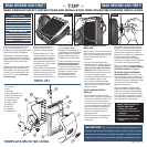
6. Insert Water Panel Evaporator
assembly into base. Make sure
bottom of scale control insert (6)
is in drain spud. Snap top of
evaporator assembly into base.
Insert feed tube into distribution
tray. See Figure 2. Rotate
nameplate (11) if necessary, so it
is right side up. Place point bypass
damper handle (8) to “WINTER”
(open) for heating season and
“SUMMER” for cooling season.
7. Control installation and wiring.
Disconnect electrical power to
furnace before wiring control.
In order for humidifier to operate,
furnace must be on and RH must
be below set-point of control.
Wiring diagrams illustrate
recommended method of
detecting furnace operation.
8. Humidifier will function with cold, hot,
softened or unsoftened water. Hot water
(140°F max) is strongly recommended to
provide maximum evaporative capacity.
Saddle valve provided may be used to tap
into water supply. See installation
instructions on saddle valve package.
Saddle valve is designed to be fully opened
or closed. Do not use to regulate flow.
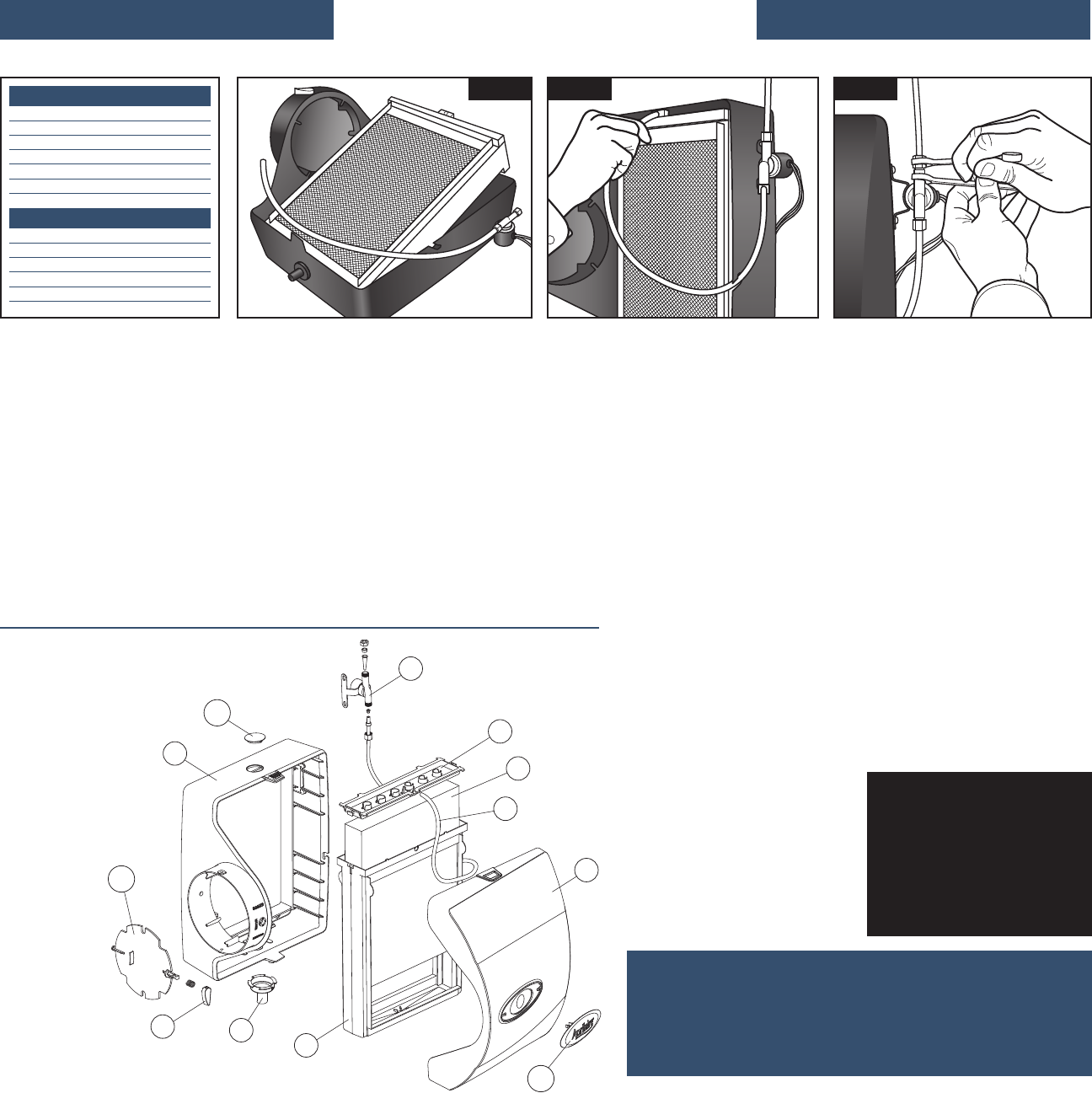
9. Run 1/4” copper tubing from saddle
valve to solenoid valve. DOUBLE-WRENCH
TO PREVENT LEAKING. See Figure 3.
10. INSTALL DRAIN IN ACCORDANCE
WITH LOCAL CODES. Run 1/2” I.D. hose
from drain spud to floor drain. Make sure
drain has constant downward slope and is
not kinked. Do not over-tighten hose clamp
onto drain spud. Do not use solvent
adhesive on drain spud.
11. Check humidifier operation. Open
saddle valve and turn control to highest
setting. Turn on furnace. Allow humidifier
to run until water flows from drain. Make
sure all electrical connections are secure
and all plumbing connections are water-
tight. Set control to proper setting.
MANUAL HUMIDIFIER CONTROL,
MODEL 500M:
Manual Control can be mounted in return
duct or on wall in living space. Knob and
cover must be removed to mount control.
See wiring diagram for 24V control
connections.
• For return duct mounting, position
template at least 6” upstream of bypass
duct connection or humidifier.Avoid
injury from sharp edges when cutting
opening. Make sure foam gasket is in
place and secure control to duct using
2 screws in openings provided.
• For wall-mount, select location that will
not be affected by drafts or heat
sources. Remove and discard foam
gasket and secure control to wall over
wire access opening using screws &
anchors provided.
DIGITAL HUMIDIFIER CONTROL,
MODEL 500:
• Select location for control on return
duct at least 6” upstream of bypass duct
connection or humidifier. Drill 3/4” hole
for sensor. Knob and cover must be
removed to mount control. Place control
on duct with RH sensor extending into
duct opening. Make sure gasket is in
place around sensor cage. Secure
control to duct using 2 screws in
openings provided.
• See wiring diagrams on template and
control instructions for 24 V control
connections.