


FURNACE
BLOWER MOTOR
MODEL 50
CURRENT
SENSING RELAY
(IF REQUIRED)
24 VAC FURNACE
ACCESSORY TERMINALS
OR TRANSFORMER
(10VA MINIMUM)
SHUT-OFF
(SADDLE VALVE)
WATER SUPPLY
YELLOW
24V SOLENOID
VALVE WIRES
IMPORTANT
USE 120 VAC POWER SOURCE OTHER THAN FURNACE MOTOR
CIRCUIT. HOWEVER, THE TRANSFORMER CAN BE POWERED
OFF THE HOT 120 VAC LINE BEFORE IT ENTERS THE FURNACE.
• DO NOT WIRE TRANSFORMER INTO FURNACE BLOWER CIRCUIT.
IMPORTANT
WHEN MODEL 50 CURRENT SENSING RELAY IS USED:
• WIRE MODEL 50 CURRENT SENSING RELAY INTO
24 VAC HUMIDIFIER CONTROL CIRCUIT ONLY!
DO NOT INSTALL IN TRANSFORMER PRIMARY CIRCUIT.
CONNECT DRAIN LINE HERE
COMMON
HI
LO
YELLOW
WIRES
G
Y
W
C
R
THERMOSTAT
110 VAC
R
C
W
Y
G
FURNACE
OUTDOOR
TEMPERATURE
SENSOR FOR
AUTOMATIC
MODE
NORTH, EAST
OR WEST SIDE
OF HOME
ABOVE EXPECTED
SNOW LINE
CONTINUOUSLY POWERED
24 VAC TRANSFORMER
PROVIDED WITH HUMIDIFIER
CONNECT TO
HOT WATER SUPPLY
CONNECT DRAIN
LINE HERE
OUTPUTSINPUTSPOWER
GWCRHHODT GfA
ADHC TERMINAL STRIP
B
READ COMPLETE SAFETY INSTRUCTIONS AND INSTALLATION TEMPLATE BE FORE STARTING INSTALLATION
This product must be installed by a qualified heating and air conditioning contractor. Failure to do so could result in serious injury from electrical shock.
This product must be installed in compliance with all local, state and federal codes.
Proper humidification and humidity control also requires that the home be constructed in accordance with local codes and good building practices.
ATTENTION INSTALLER:
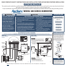
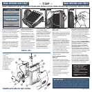
MODEL 500 SERIES HUMIDIFIER
TheModel500and500MAprilairecanbe
installedoneitherthesupplyorreturn
plenumofa forcedairhandlingsystem and
iseasilyreversible for installationwith
right handor left hand bypass duct
connections. The humidifierdimensions
andserviceability must be considered
when selectingthe best locationfor the
humidifier.Hereare2 examples ofmany
types of installations.
RESEARCH PRODUCTS CORPORATION • P.O. BOX 1467 • MADISON, WI 53701-1467 • CALL 800/334-6011 • FAX 608/257-4357
RETURN
SUPPLY
S
RETURN
R
SUPPLY
S
Horizontal
Upflow
90-120790-1510
90-1079
WARNING
1. ELECTRICAL SHOCK HAZARD.
Disconnect electrical power to the
furnace before starting installation.
Failure to do so could result in
serious injury from electrical shock.
2.
SHARP EDGES HAZARD. Sharp
edges may cause serious injury from
cuts. Use care when making plenum
openings and handling ductwork.
3.
RISK OF SCALDING. Water
temperature over 125°F can cause
severe burns and scald instantly.
Shut off the hot water supply before
disconnecting or tapping into any
hot water supply line.
SPECIFICATIONS
H
UMIDIFIER DIMENSIONS
Width (includingsolenoid valve): 15
5
⁄8”
Height
(includingdrainspud): 13”
Depth
: 10
1
⁄4”
BYPASS DUCT OPENING
6” diameter
PLENUM OPENING
9
1
⁄2”W x 9
1
⁄2”H
WATER FEED RATE
3 gph
ELECTRICAL DATA
24 VAC-60 Hz, 0.5 AMP
CAUTION
1. Do not install humidifier where freezing temperatures
could occur. The water line could freeze and crack
causing water damage to the home.
2. Do not install humidifier or bypass connection on the
furnace jacket.
3. Do not install humidifier or bypass connection on a
plenum face where the blanked off ends of the cooling
coil will restrict air movement through the humidifier.
4. Do not set humidity level above recommended or to
recommended level if condensation exists on inside
windows of any unheated space, as condensation
damage may result. Excess humidity can cause
moisture accumulation which can allow the possibility
for mold growth in the home.
5. Do not connect Model 500 or 500M transformer
to blower motor wiring. Premature component
failure may result.
6. When installing Humidifier Control on downflow
furnace, ensure blower continues to run after a
heatcallissatisfied toeliminate high temperatures
from damaging the Humidifier Control.
7. Do not install humidifier where water pressure
exceeds 125 psi, since damage to the humidifier
may result. Follow codes in effect concerning
pressure reduction.
8. Do not install humidifier on systems with
greater than 0.4 in. wg pressure differential
between supply and return plenums.
RISK OF PROPERTY AND EQUIPMENT DAMAGE.
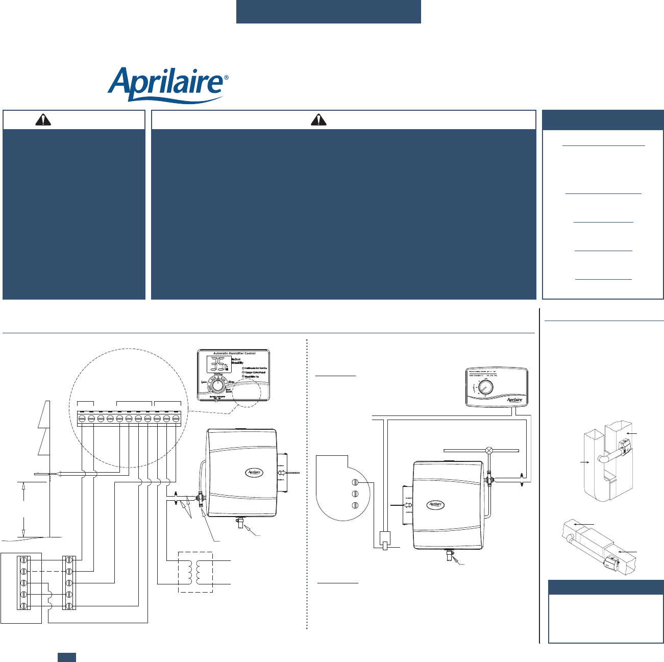
INSTALLATION OPTIONSRECOMMENDED WIRING DIAGRAMS
(SEE STEP 7 ON BACK AND “HUMIDIFIER CONTROL SAFETY AND INSTALLATION INSTRUCTIONS” FOR DETAILED WIRING INSTRUCTIONS)
Model 500M
MANUAL CONTROL
Model 500
DIGITAL HUMIDIFIER
CONTROL
NOTE
When installingtheAprilaire humidifier
with theAprilaireDigitalHumidifier
Controlorona heatpumpsystem,use
hotwater.Theheatedwatersupplements
thereducedsupplyairtemperature as
addedheatforevaporation.