5
INSTALL THE UNIT BASE
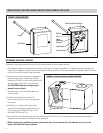
1. Using the Unit Base as a guide, mark the locations for the lamp and mounting holes on the rooftop unit cabinet.
2. Carefully inspect the inside of the rooftop unit and make sure that no damage to any components will occur as a result of
drilling the holes.
3. Drill hole for the lamp using a 2 in. hole cutter. At the mounting hole locations, use 3/32 in. drill bit to make pilot holes for
mounting screws.
4. Apply weatherproof sealant (not provided) to the side of the Unit Base that is in contact with the rooftop unit housing.
Mount the Unit Base to the rooftop unit using #10 sheet metal screws.
MAKE ELECTRICAL CONNECTIONS
1. Verify power to the HVAC equipment is shut off. Determine where the power for the unit will come from. The units can use
any voltage from 120 VAC up to 277 VAC (single phase), 60 Hz. The ballast automatically adjusts to whatever voltage is supplied in
that range. The units must be wired such that the disconnect switch of the air handler is also the disconnect switch
for the UV lamp. Additionally, to prevent accidental exposure to UV germicidal light, it is recommended that safety
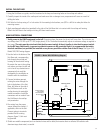
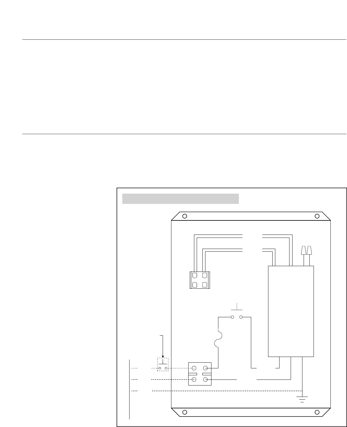
interlock switches (not provided) be installed on any access panel door within view of the UV lamp. See Figure 3 for
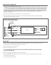
Model 1952/1953 wiring diagram.
2. Use the hole in the bottom of the
Unit Base and a corresponding
hole through the rooftop unit
housing for the electrical wiring.
Be certain the area in the rooftop
unit where you intend to drill and
cut is free of any obstructions or
components that would be
damaged by the installation or
interfere with the installation.
3. If space limitations prevent
running the wires through the
hole in the bottom of the Unit
Base, drill holes in the side of
the Unit Base as well as the
rooftop housing for watertight
conduit connectors. Install the
connectors and run conduit from
the Unit Base to the rooftop
unit penetration.
4. Run wiring from the power
source through the conduit, if
applicable, and into the Unit.
Connect wiring to terminals
provided. Refer to wiring
diagram, Figure 3. Unit must
be grounded.
5. Shield non-metallic components (such as electrical wires and fan belts) that receive direct or reflected UV radiation with
aluminum tape, sheet metal, or conduit.
White
Green
Black
Red (2)
Blue (2)
Yellow (2)
NOT USED
Lamp Socket
Ballast
3A Fuse
Interlock Switch
White
Black
Green
Ground
Interlock switches
(not provided)
recommended for
all access panel
doors
120VAC to
277VAC
Power Source
FIGURE 3 – Model 1952/1953 Wiring Diagram
90-753


