


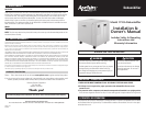
Use the main control knob (Figure 2) on the outside of the unit
to set the dehumidifier dryness setting. Start with a “NORMAL”
setting for most installations. Moving the knob clockwise to
“MORE” will make conditions drier. Moving the knob toward
“LESS” allows for higher moisture levels.
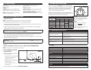
Based on the indoor temperature, use the following table to
determine the control knob setting to reach the desired RH value.
The dehumidifier will work to achieve these values.
EXAMPLE: At an indoor temperature of
75°F with a dehumidifier control knob
setting of 3, the dehumidifier will work to
achieve an RH value of 53%.
NOTES:
1. %RH values are ±5% and are to be
used as a GUIDE ONLY for initial
set-up.
2. Indoor Temperature is measured at the
inlet to the dehumidifier.
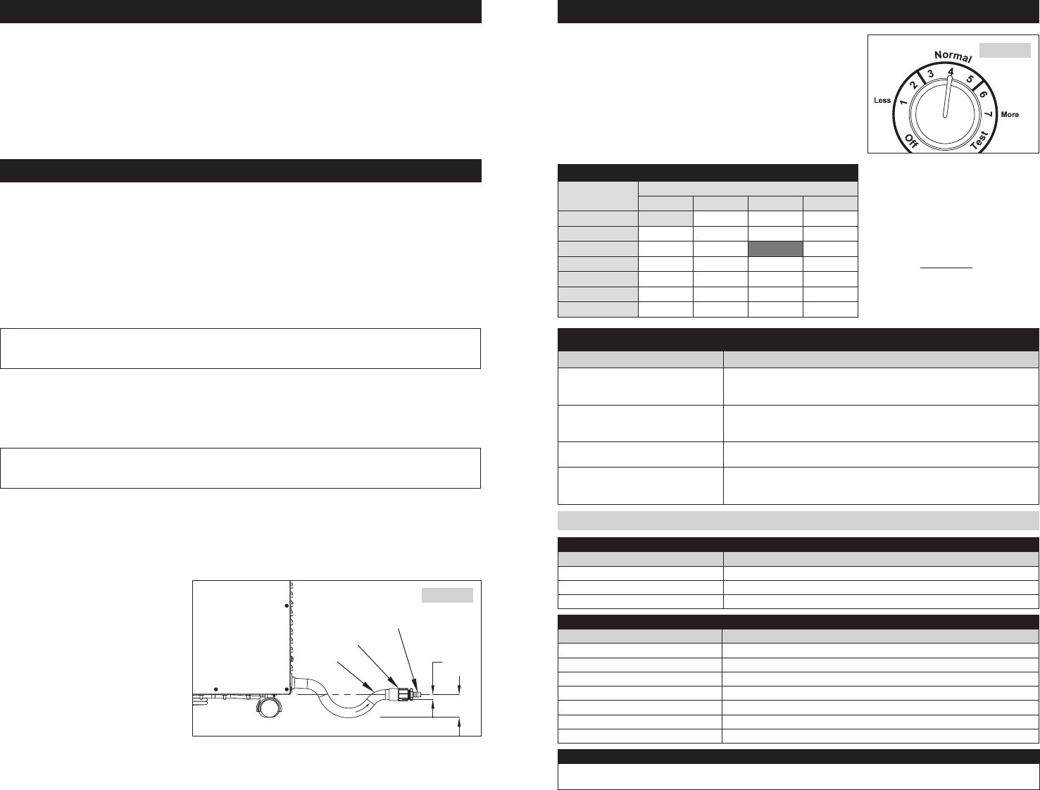
1. Install the drain line
NOTE: The provided condensate trap must be installed to the dehumidifier.
• Verifythebottomofthedehumidifieris2
1
/2” or higher above the floor.
• Insertthehighsideofthetrapintothedrainoutlet(waterflowdirectionisshownonthetrapand
should point away from the dehumidifier)
• Ifthereisnotenoughroomtoinstallthetrapdirectlyintothedehumidifier,usetheprovided90°
elbow to position the trap close to the dehumidifier
IMPORTANT: The bottom of the trap outlet must be at least
1
/2 inch below the bottom of the
dehumidifier to ensure a proper drainage slope (see Figure 1).
• Afterverifyingthatthetrapisintheproperorientation,usePVCprimerandcementtosecurethe
trap in place. Cement the supplied threaded coupler to the outlet of the trap.
• Screwthesuppliedhosebarbfittingintothecouplerandattachthesupplied
1
/2 inch I.D. drain hose.
Route the hose to the nearest drain.
IMPORTANT: To prevent a pressure lock within the drain line, the tube MUST be installed with a
constant downward slope.
Prime the drain system by filling the drip pan in the dehumidifier with water until flow is completed to
the drain.
2. Plug the dehumidifier directly into an outlet – DO NOT USE AN EXTENSION CORD.
NOTE: A 15 amp circuit is required for proper operation.
3. Turn the ON/OFF switch to ON.
4. System Checkout:
• Rotatethecontrolknobclockwiseto
the “Test” position.
a. The blower will start immediately
and after three minutes the
compressor will start.
b. Both will run for one minute then
both will shut off.
c. Turn the control knob to the
desired setting.
• Iftheunitdoesnotrun,refertotheTroubleshooting Guide.
V. TROUBLESHOOTING GUIDE
SYMPTOM TROUBLESHOOTING PROCEDURE / POSSIBLE REASON
Dehumidifier is producing hot air
•Reheatofoutgoingairwillcauseatemperatureincreasesacrossthedehumidifier
•Unitwillpossiblyruncontinuouslyinitially.Afterunithas“dried”home,dehumidifier
will cycle, reducing load
Dehumidifier not adequately dehumidifying
•Unit will need time to “dry” materials in home before effectively changing RH.
•Compressorisnotturningon
•Systemundercharged
Dehumidifier is not draining properly
•Checkcondensatetraptobesureitisclear
•Checkdrainlineforcontinuousslope
Dehumidifier does not run
•Follow all of the system checkout procedures. Make sure power switch is on!
•Checkthatcircuitbreakerisnottripped.Thedehumidifierrequiresaminimumof
8 amps. The dehumidifier should be placed on its own dedicated 15 amp circuit
III. INSTALLATION INSTRUCTIONS
IV. OPERATING INSTRUCTIONS
BARBED FITTING
COUPLER
TRAP
1/2”
2-1/2”
W
A
T
E
R
F
L
O
W
90-1393
FIGURE 1
Dimensions: 20
3
/4” W x 24” L x 20
3
/8”–23
5
/8” H
Weight: 93lbs.
Capacity: 90pintsperday@60%RH,80˚F
(ANSI/AHAM DH-1-2003 standard conditions)
Power: 115 VAC, 8 Amps, Unit is equipped
with an 8 ft. grounded cord.
Design Airflow: 275CFM@0.6in.w.c.
Filter: MERV 8 Filter
Cabinet Insulation: 1” foil faced EPS insulation
Inlet Air Operating Conditions: 40˚Fto105˚F
Ambient Air Operation Conditions: 40˚Fto150˚F
II. SPECIFICATIONS
90-1327
FIGURE 2
%RH (± 5%) based on Control Knob Setting and Indoor Temperature
Control Knob
Setting
Indoor Temperature
65°F 70°F 75°F 80°F
1 – “LESS” 84% 71% 60%
2 86% 73% 61% 52%
3 – “noRMaL” 74% 63%
53%
45%
4 – “noRMaL” 64% 54% 45% 39%
5 – “noRMaL” 55% 46% 39% 33%
6 47% 39% 33% 28%
7 – “MoRE” 40% 34% 28% 24%
Green LED
Activity Status
ON Solid Compressor ON
Blinking 1 second on, 1 second off Sampling
Blinking 1/2 second ON, 1/2 second OFF Defrosting
Test Mode
At the end of test mode (3 minutes of DEH Fan + 1 minute of Compressor ON & DEH Fan), the Red and Green LEDs will turn ON
and OFF alternately until the knob has been turned away from “TEST”.
Red LED
Activity Status
1 Blink every 5 seconds There is an error with the RH sensor
2 Blinks every 5 seconds The board temperature sensor is opened or shorted
3 Blinks every 5 seconds The Model 70 Living Space Control fails to respond after 3 consecutive attempts
4 Blinks every 5 seconds The refrigerant charge has been detected as low
5 Blinks every 5 seconds The temperature sensor is out of the operating range
6 Blinks every 5 seconds The internal frost sensor is opened or shorted
7 Blinks every 5 seconds The float switch has opened
LED CODES