


www.aosmithinternational.com
X
Y
V
W
X
Y
V
W
W
Y
V
X
Z
Y
T
X
Data subject to change INT/1108/SGS/02
Terms and conditions apply, please refer to our website.
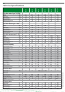
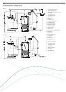
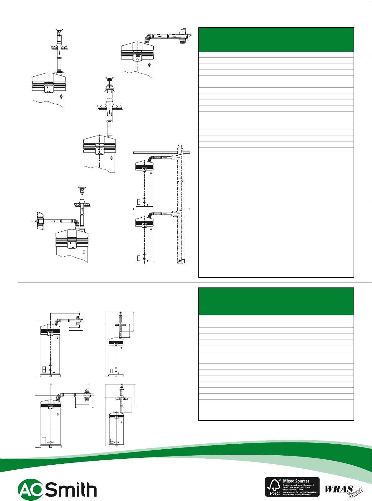
Flue systems SGS
Installation options
B23
C13
C33
C53
C43
A SGS water heater should be installed according category B23,
C13, C33, C43 or C53*.
Concentric
Diameter (mm) 80/125 100/150 100/150 100/150 130/200 130/200
Max. length (m) 40 40 40 15 15 15
Max. 45/90° bends 7 7 7 4 3 3
Parallel (standard diameter)
Diameter (mm) 80 100 100 100 130 130
Max. length (m) 25 80 45 25 115 60
L
equivalent
/bend 90° (m) 3,9 4,6 4,6 4,6 2,4 2,4
L
equivalent
/bend 45º (m) 1,1 1,2 1,2 1,2 1,4 1,4
Parallel (larger diameter for more length)
Diameter (mm) 100 130 130 130 150 150
Max. length (m) 100 100 100 100 100 100
L
equivalent
/bend 90º (m) 4,6 2,4 2,4 2,4 2,6 2,6
L
equivalent
/bend 45º (m) 1,2 1,4 1,4 1,4 1,6 1,6
* All SGS are also approved for installations where the unit is supplied
without venting materials (C63).
Concentric flues
It is not permitted to use more than the specified number of
bends, even when the duct is shorter than the maximum
length. A 45° bend is equivalent to a 90° bend.
Parallel flues
- The maximum permissible length should be reduced by the
equivalent length of each bend. (Note: for a parallel installation
this means that 3 changes in direction amount to 6 bends
(3 in the supply duct and 3 in the flue).
- The maximum length also applies if a parallel installation has
different supply and flue duct lengths (B23, C53).
- Combined flues (C43) shall be fitted with a condensate drain.
Note: horizontal flue runs must be installed with a fall of at least
5 mm per metre.
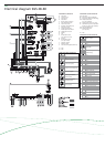
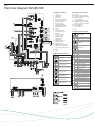
SGS 28
SGS 30
SGS 50
SGS 60
SGS 80
SGS 100
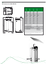
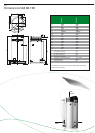
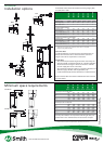
Flue systems SGS
Minimum space requirements
SGS 28
SGS 30
SGS 50
SGS 60
SGS 80
SGS 100
Minimal space for wall duct (mm)
V 550 550 550 550 640 640
W 725 790 790 790 940 940
X 1630 2170 2170 2170 2230 2230
Y 1460 1480 1480 1480 1620 1620
Y * 1010 1030 1030 1030 1170 1170
Minimal space for roof duct (mm)
V 1305 1500 1500 1500 1730 1730
W 680 1035 1035 1035 1120 1120
X 3060 3420 3420 3420 3620 3620
X ** 2110 2470 2470 2470 2670 2670
Y 1575 1415 1415 1415 1560 1560
Y ** 625 465 465 465 610 610
For the parts numbers of components and flue gas ducts, etc.
please refer to the “Maintenance and accessories” chapter.
* Distance without concentric pipe between bend and wall duct.
** Distance without concentric pipe between appliance and roof duct.
Ø80/125 Ø100/150 Ø100/150 Ø100/150 Ø130/200 Ø130/200
SGS 28-60
SGS 80-100