


24
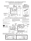
SYSTEM DIAGNOSTICS
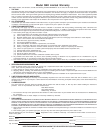
Your water heater is equipped with an ignition module that
incorporates a diagnostic system to assist in troubleshooting
the appliance. The indicator codes on the ignition module are
as follows:
1 flash System lockout (retries or cycles exceeded)
2 flashes Pressure switch stuck close
3 flashes Pressure switch stuck open
4 flashes Open on high temperature limit switch (eco)
6 flashes 115 volt AC power reversed (check polarity)
7 flashes Low flame sense signal (make sure flame
sensor is in burner flame)
8 flashes Check ignitor
continuous flash -> continuous flame sensed > 5 seconds
without gas valve
continuous on -> internal control failure - replace ignition control
module.
Use this diagnostic system in conjunction with the
“OPERATIONAL CHECKLIST” and the “SEQUENCE OF
OPERATION” to troubleshoot the appliance.
SERVICE
The installer may be able to observe and correct certain problems
which may arise when the unit is put into operation. HOWEVER,
it is recommended that only qualified servicemen, using
appropriate test equipment, be allowed to service the heater.
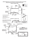
As preliminary step, check wiring against diagram, check for
grounded, broken or loose wires. Check all wire ends to be
sure that they are making good contact.
ELECTRICAL SERVICING
CAUTION
LABEL ALL WIRES PRIOR TO DISCONNECTION WHEN
SERVICING CONTROLS. WIRING ERRORS CAN CAUSE
IMPROPER AND DANGEROUS OPERATION.
VERIFY PROPER OPERATION AFTER SERVICING.
REPLACEMENT PARTS
Replacement parts may be ordered through State dealers,
unauthorized servicers or distributors. Refer to the Yellow
Pages for where to call or contact the State Water Water Heaters,
500 Lindahl Parkway, Ashland City, TN 37015, 1-800-821-2017
or visit our website at www.statewaterheaters.com. When
ordering parts be sure to state the quantity, part number and
description of the items including the complete model and serial
number as it appears on the product. Refer to the parts list for
more information.
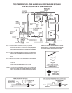
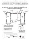
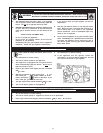
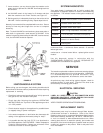
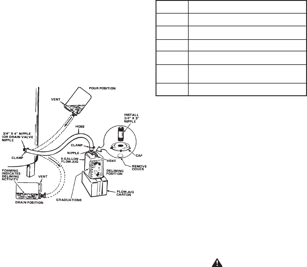
7. Lower container, you may have to place the container on its
empty carton to prevent the UN•LIME from flowing back into
the container.
8. Let UN•LIME remain in the heater for 5 minutes and then
lower the container to the "Drain" Position, see Figure 15.
9. Deliming activity is indicated by foaming on the surface of the
UN•LIME. If there is deliming activity, repeat steps 6 thru 8.
Normally, lime removal will be completed within one hour. Severe
build-up of lime may take longer than an hour to complete
descaling.
Note: To check UN•LIME for continued use, place some scale or
white chalk in a glass with a small amount of UN•LIME. If the
material is vigorously dissolved by the UN•LIME, it can be reused;
if not, the UN•LIME should be replaced.
FIGURE 15
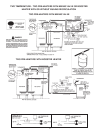
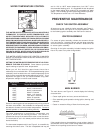
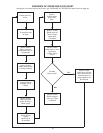
IGNITION MODULE SYSTEM
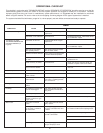
Before calling your service agent, the following checklist should
be examined to eliminate obvious problems from those requiring
replacement or servicing.
— Check that “main manual gas shutoff valve” is fully open and
that gas service has not been interrupted.
— Check that after following the appliance OPERATING
INSTRUCTIONS, the “Top Knob” of the appliance gas valve
is in “ON” position.
— Check electrical supply to the appliance for possible blown
(or tripped) fusing or power interruption.
— Is the water temperature in tank below the thermostat dial
setting on the appliance thermostat (calling for heat)?
— It is possible that the high limit (E.C.O.) has functioned to
shut off the appliance. See FEATURES — Water Temperature
Control for reset procedure. Contact your serviceman if limit
continues to function to shut off appliance.