


5
4
6
4
C
F
G
3
4
9
B
17
11
14
14
14
12
A
E
4
18
19
H
T
5
4
6
4
A
C
F
G
3
B
4
1
5
15
16
A
11
14
14
14
12
T
9
www.aosmithinternational.com
Data subject to change INT/0808/ITE/01
Terms and conditions apply, please refer to our website
ITE
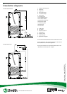
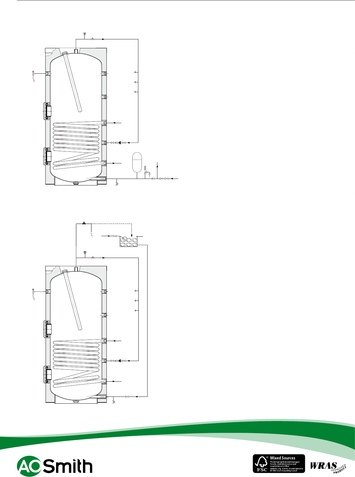
Installation diagrams
1 Pressure reducing valve
3 T&P valve
4 Stop valve
5 Non-return valve
6 Circulation pump
9 Drain valve
11 Isolating valve
12 Temperature gauge
14 Hot water outlets
15 Expansion relief valve
16 Expansion vessel
17 Three way valve
18 Water tank
19 Float valve
A Cold water
B Hot water
C Return circulation
F Primary flow
G Primary return
E Over flow pipe
H Expansion vent pipe
A.O. Smith unvented system kits utilise combination valves.
Further installation and connection details can be found in
the Installation & Commissioning Manual.
For the parts numbers of components please refer to the
“Maintenance and accessories” chapter.
ITE 400-1000 vented
ITE 400-1000 unvented