5454
5454
54
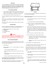
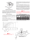
To adjust the flow rate setting:
1. Remove the flow switch cover.
2. For higher flow rate—turn the range adjusting screw clockwise.
3. For lower flow rate—turn the range adjusting screw
counter-clockwise.
CAUTION
The switch is factory set at approximately the minimum flow rate,
see Table II. It must not be set lower than the factory setting as this
may result in the switch failing to return at a “no flow” condition.
4. Replace the flow switch cover.
Where units are installed in multiples, each boiler must be
individually protected by a safety flow switch.
SAFETY RELIEF VALVE MAINTENANCE
Every six months the system safety relief valves should be checked
to ensure that they are in operating condition. To check a relief
valve, lift the lever at the end of the valve several times. The valve
should seat properly and operate freely.
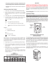
CAUTION
BEFORE MANUALLY OPERATING A RELIEF VALVE, MAKE SURE
THAT A DRAIN LINE HAS BEEN ATTACHED TO THE VALVE TO
DIRECT THE DISCHARGE TO AN OPEN DRAIN. FAILURE TO
TAKE THIS PRECAUTION COULD MEAN CONTACT WITH
EXTREMELY HOT WATER EXITING THE VALVE DURING THIS
CHECK OPERATION.
If a relief valve discharges periodically or continuously, it may be
due to thermal expansion of water in a closed water supply system,
or, it may be due to thermal expansion of water in a closed water
supply system, or, it may be due to a faulty relief valve.
Thermal expansion is the normal response of water when it is
heated. In a closed system, thermal expansion will cause the
system pressure to build until the relief valve actuation pressure is
equaled. Then, the relief valve will open, allowing some water to
escape, slightly lowering the pressure.
A properly sized expansion tank should be installed.
ABOVE ALL, DO NOT PLUG ANY RELIEF VALVE. THIS IS NOT A
SOLUTION AND CAN CREATE A HAZARDOUS SITUATION.
REPLACEMENT PARTS
U.S. Models
Replacement parts may be ordered through A. O. Smith dealers,
authorized servicers or distributors. Refer to the Yellow Pages for
where to call or contact the A. O. Smith Water Products Company,
5621 W. 115th Street, Alsip, IL 60803, 1-800-433-2545. When
ordering parts be sure to state the quantity, part number and
description of the item including the complete model and serial
number as it appears on the product. Refer to the parts lists for
more information.
Canadian Models
Replacement parts may be ordered through A. O. Smith dealers,
authorized servicers or distributors. Refer to the Yellow Pages for
where to call or contact the A. O. Smith Enterprises, Ltd., P. O. Box
310, 768 Erie St., Stratford, Ontario N5A 6T3, 1-800-265-8520.
When ordering parts be sure to state the quantity, part number and
description of the item including the complete model and serial
number as it appears on the product. Refer to the parts lists for
more information.
QUALITY REPLACEMENT PARTS
At the time of removal of an existing boiler, the following steps shall
be followed with each appliance remaining connected to the
common venting system placed in operation, while the other
appliances remaining connected to the common venting system
are not in operation.
Seal any unused openings in the common venting system.
Visually inspect the venting system for proper size and horizontal
pitch and determine there is no blockage or restriction, leakage,
corrosion and other deficiencies which could cause an unsafe
condition.
Insofar as is practical, close all building doors and windows and
all doors between the space in which the appliances remaining
connected to the common venting system are located and other
spaces of the building. Turn on clothes dryers and any appliance
not connected to the common venting system. Turn on any exhaust
fans, such as range hoods and bathroom exhausts, so they will
operate at maximum speed. Do not operate a summer exhaust
fan. Close fireplace dampers.
Place in operation the appliance being inspected. Follow the
lighting instructions. Adjust thermostat so appliance will operate
continuously.
Test for spillage at the draft hood relief opening after 5 minutes of
main burner operation. Use the flame of a match or candle, or
smoke from a cigarette, cigar or pipe.
After it has been determined that each appliance remaining
connected to the common venting system properly vents when
tested as outlined above, return doors, windows, exhaust fans,
fireplace dampers and any other gas-burning appliance to their
previous condition of use.
Any improper operation of the common venting system should be
corrected so the installation conforms with the National Fuel Gas
Code, ANSI Z223.1 and/or CAN/CGA B149, Installation Codes.
When resizing any portion of the common venting system, the
common venting system should be resized to approach the
minimum size as determined using the appropriate tables in
Appendix F in the National Fuel Gas Code, ANSI Z223.1 and/or
CAN/CGA B149 Installation Codes.
REMOVAL OF EXISTING BOILER FROM A COMMON VENTING SYSTEM


