8
Troubleshooting
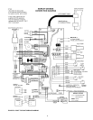
The WHC1502 Series Control System has many inherent diagnos-
tic and fault detection routines built into its operating hardware and
software. These routines, in conjunction with the four (4) digit LED
display and eleven (11) LED status indicators on the Display Board,
can greatly assist any service person in quickly pinpointing the source
of a problem which may occur within the appliance. Under certain
circumstances, multiple LED’s will illuminate to better pinpoint the
target area(s).
The following list defines the error code messages that scroll across
the LED display:
ERROR MESSAGE REPORTED ERROR
OPEn InLEt ProbE No probe detected at connec-
tor CN1 on Control Board.
OPEn OutLEt ProbE No probe detected at connec-
tor CN2 on Control Board.
Circulation FAIL No flow detected at flow
switch.
Inducor FAIL No pressure detected at pres-
sure switch.
FLAmE SenSE FAIL Flame sense detected before
gas valve is turned on.
SenSor FAIL One of the sensors, Flow,
Pressure, Hi Gas, or Lo Gas
was not in the correct state.
Ignitor FAIL No Ignitor current sensed.
No Ignition Flame not detected after 1 or
3 tries.
ECO FAIL ECO/High Limit switch
opened.
Control FAIL Relay did not open or close
properly.
BLOCKED VENT SHUT-OFF SYSTEM
The Boiler is equipped with a blocked vent shut-off system which
will close the gas valve and shut off the main burner gas when there
is excessive pressure in the vent system due to a partially or
completely blocked vent system. The DIA-SCAN II display on the
front panel will indicate this failure condition.
DO NOT ATTEMPT TO OPERATE THE BOILER if this situation
occurs. Shut the boiler off before performing all the steps shown
in "TO TURN OFF GAS TO APPLIANCE" section of the Lighting
and Operating Instructions.
Contact a qualified service agent to inspect the unit and vent system
and correct the problem.
VENT SYSTEM
The flue products are corrosive in nature and if the boiler is vented
horizontally the flue gases are at a higher pressure than the
surrounding air pressure. Inspection of the boiler and vent system
is necessary to insure that flue gas leakage to the surrounding area
does not occur.
Inspect the external surfaces of the vent system every 3 months for
corrosion and leakage. Inspect the vent terminations for corrosion
and foreign matter which may be blocking the exhausting flue
products. Call a qualified service agent to replace or repair any
corroded or leaking parts.
Qualified service agent must inspect internal surfaces of the vent
system and the boiler at least once a year.
BURNER SYSTEM
To maintain safe operation and the greatest efficiency for the boiler,
observe the burner flame through the observation port on the left
jacket panel, once a month for proper flame characteristics.
The burners should display the following characteristics:
• Provide complete combustion of gas.
• Cause rapid ignition and carry over across all burners and across
the entire burner.
• Give quiet operation during ignition, burning and extinction.
• Cause no excessive lifting of flames from the burner ports.
If the preceding characteristics are not evident, check for
accumulation of lint or other foreign material that restricts the inlet
air or burner ports. Ensure there is the proper amount of air to
the burner. Flame lifting from the burner is caused by too much
air to the burner.
The burners must be inspected by a qualified service technician at
least once a year.
DO NOT STORE COMBUSTIBLE MATERIALS, GASOLINE, OR
OTHER FLAMMABLE VAPORS, LIQUIDS IN THE AREA OF THE
APPLIANCE. NONCOMPLIANCE MAY RESULT IN FIRE OR
EXPLOSION. DO NOT OBSTRUCT THE FLOW OF COM-
BUSTION OR VENTILATION AIR TO THE APPLIANCE
.
CHEMICAL VAPOR CORROSION
Boiler corrosion and component failure can be caused by airborne
chemical vapors. Spray can propellants, cleaning solvents,
refrigerants, calcium or sodium chloride (water softener salts),
waxes, and process chemicals are typical compounds that are
potentially corrosive. These materials are corrosive at very low
concentration levels with little or no odor to reveal their presence.
Products of this sort should not be stored near the boiler. Air which
is brought in contact with the boiler should not contain any of these
chemicals. The boiler should be provided with air from outdoors
when installed in environments having corrosive atmospheres.
CIRCULATION PUMP
Refer to the pump manufacturer's schedule of maintenance for
frequency and method of lubricating the pump and motor. Inspect
the pump once a month for leaky mechanical seals and/or O-rings
and loose or damaged components. Contact a qualified service
agent to replace or repair parts as required.


