


6
1.2 Technical safety
equipment
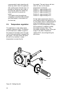
1.2.1 Gas control valve
The water heater has been fitted with a
gas control block consisting of a
thermo-electrical pilot flame safeguard,
pilot flame pressure regulator, burner
pressure regulator, a control thermostat
(adjustable between 40°C and 80°C)
and a safety thermostat (90°C). This
gas control block with its simple and
secure control respectively switches
the gas supply to the main burner on or
off.
This gas control block is suitable for
gasses from the first, second and third
gas family. The maximum inlet pressure
is 50 mbar.
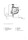
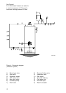
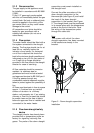
1.2.2 Flue down draught safety
device
The appliance is fitted with a flue down
draught safety device. The operation of
the safeguard is based on the principle
of the Thermal Reflux Safeguard
(T.R.S.).
The appliance has been fitted with a
T.R.S., see Figure 2.
This T.R.S. can be recognized by the
brass colored helix coil which is
connected to the lower edge of the
draught diverter. The helix coil has been
connected to the thermostat by means
of a capillary tube. The wiring of the
thermostat has to be connected to the
couple circuit before the heater is put
into operation.
It is the aim of the T.R.S. to prevent flue
gasses from the water heater entering
the room where the water heater has
been placed, instead of passing through
the flue to outside atmosphere. The
thermo-couple circuit is interrupted and
the gas supply is disconnected as soon
as the T.R.S. is activated by heating of
the sensor by the hot gasses.
After the cause of the reentry of flue
gasses has been traced the device can
be put back into operation again. In case
of T.R.S. the RESET button has to be
pressed first.
If this failure occurs frequently, this
indicates that the flue suffers from
down draught conditions. We advice
that necessary remedial actions be
carried out by a competent person.
Important
The T.R.S. should never be put out
of operation. Reentry of flue
gasses to the building could be
harmful and cause poisoning or
death.