


13
ELECTRICAL
GENERAL
The installation must conform to these instructions, the local
code authority having jurisdiction, and the requirements of the
power company. In the absence of code requirements follow
the latest version of NFPA-70,
The National Electrical Code
which may be ordered from: American National Standards
Institute, 1430 Broadway, New York, NY 10018.
WARNING
AN ELECTRICAL GROUND IS REQUIRED TO REDUCE RISK
OF ELECTRIC SHOCK OR POSSIBLE ELECTROCUTION. The
water heater should be connected to a separate, grounded,
branch circuit with overcurrent protection and disconnect switch.
The water heater should be grounded in accordance with
national and local codes.
Check the heater model and rating plate information against
the characteristics of the branch circuit electrical supply. DO NOT
CONNECT THE HEATER TO AN IMPROPER SOURCE OF
ELECTRICITY.
Voltage applied to the heater should not vary more than +5% to
-10% of the model and rating plate marking for satisfactory
operation.
DO NOT ENERGIZE THE BRANCH CIRCUIT FOR ANY REASON
BEFORE THE HEATER TANK IS FILLED WITH WATER. DOING
SO WILL CAUSE THE HEATING ELEMENT TO BURN OUT.
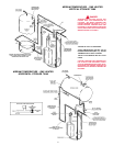
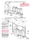
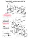
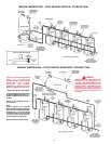
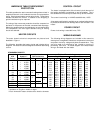
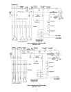
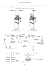
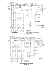
The branch circuit is connected to the heater wiring through an
opening provided on the heater.
BRANCH CIRCUIT
The branch circuit wire and fuse size should be established
through reference to the latest version of the
National Electrical
Code or other locally approved source in conjunction with the
heater amperage rating. Branch circuit wires should be 75°C
temperature rated. For convenience, portions of the wire size
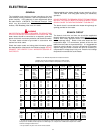
tables from the Code are reproduced here. It is suggested the
electrician size the branch circuit at 125 percent of the heater
ampere rating and further increase wire size as necessary to
compensate for voltage drop in long runs. Branch circuit voltage
drop should not exceed 3% at the heater.
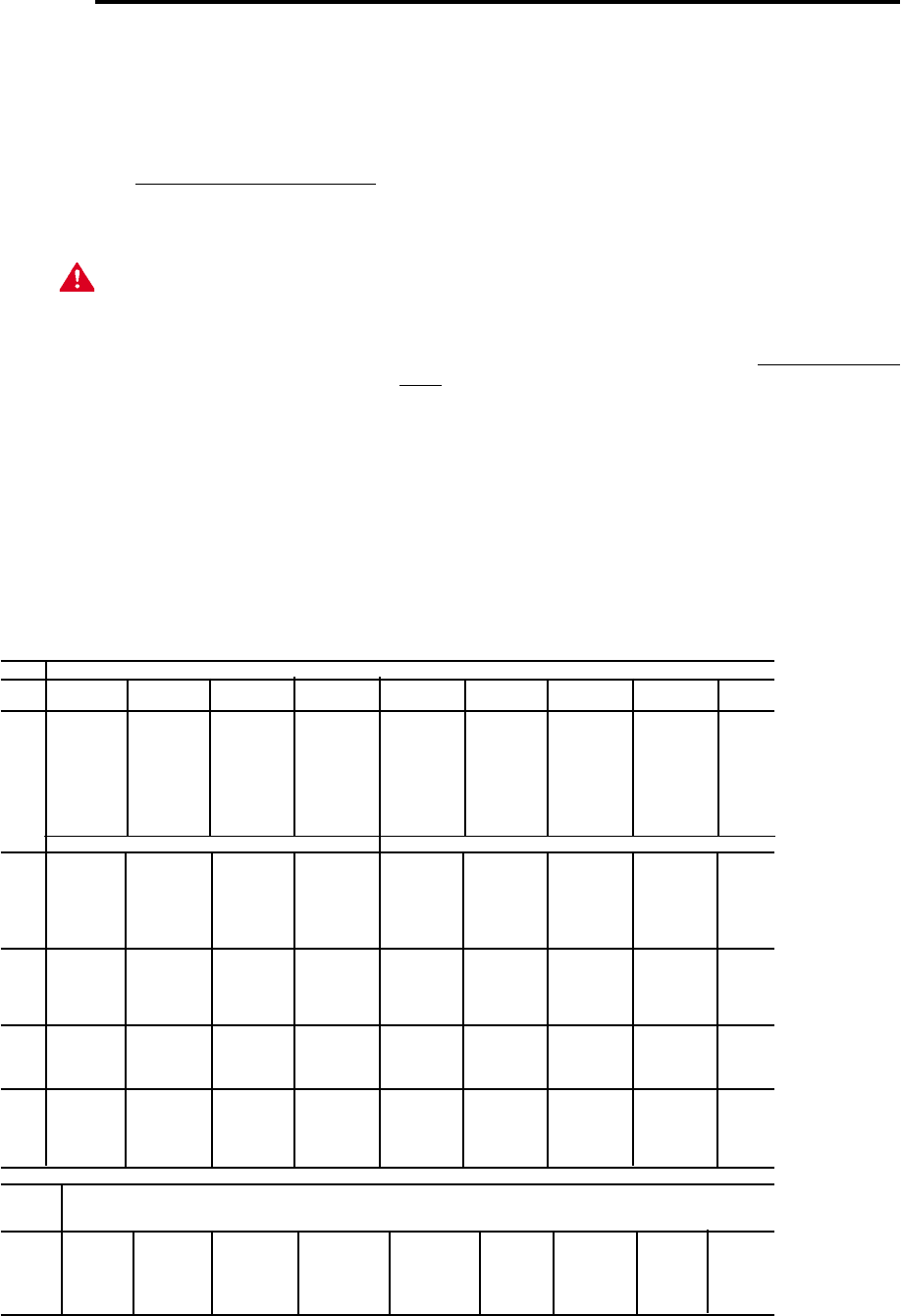
TABLE 310-16. Allowable Ampacities of Insulated Conductors
Not More Than Three Conductors in Raceway or Cable or Earth
(Directly Buried), Based on Ambient Temperature of 30°C (86°F)
Size Temperature Rating of Conductor, See table 310-13 Size
60°C 75°C 85°C 90°C 60°C 75°C 85°C 90°C
(140°F) (167°F) (185°F) (194°F) (140°F) (167°F) (185°F) (194°F)
TYPES TYPES TYPES TYPES TYPES TYPES TYPES TYPES
RUW, T FEPW V, MI TA, TBS RUW, T RH, RHW V, MI TA, TBS,
AWG TW, UF RH,RHW SA, AVB TW, UF RUH SA, AVB
RUH, SIS, =FEP, THW, SIS, AWG
THW, =FEPB, THWN =RHH,
MCM THWN, =RHH, XHHW, =THHN, MCM
XHHW =THHN, USE =XHHW*
USE, ZW =XHHW*
COPPER ALUMINUM OR COPPER-CLAD ALUMINUM
18 …… …… …… 21 …… …… …… …… ……
16 …… …… 22 22 …… …… …… …… ……
14 15 15 25 25 …… …… …… …… ……
12 20 20 30 30 15 15 25 25 12
10 30 30 40 40 25 25 30 30 10
840 4550 50 304040 408
655 6570 70 405055 556
470 8590 90 556570 704
3 80 100 105 105 65 75 80 80 3
2 115 120 120 75 90 95 95 2
1 130 140 140 100 110 110 1
0 150 155 155 120 125 125 0
00 175 185 185 135 145 145 00
000 200 210 210 155 165 165 000
0000 230 235 235 180 185 185 0000
250 255 270 270 205 215 215 250
300 285 300 300 230 240 240 300
350 310 325 325 250 260 260 350
400 335 360 360 270 290 290 400
500 380 405 405 310 330 330 500
CORRECTION FACTORS
Ambient For ambient temperatures over 30°C, multiply the amacities shown by the appropriate Ambient
Temp.°C correction factor to determine the maximum allowable load current. Temp.°F
31-40 .82 .88 .90 .91 .82 .88 .90 .91 86-104
41-50 .58 .75 .80 .82 .58 .75 .80 .82 105-122
51-60 …… .58 .67 .71 …… .58 .67 .71 123-141
61-70 …… .35 .52 .58 …… .35 .52 .58 142-158
71-80 …… …… .30 .41 …… …… .30 .41 159-176
= The load current rating and the overcurrent protection for these conductors shall not exceed 15 amperes for 14 AWG,
20 amperes for 12 AWG, and 30 amperes for 10 AWG copper; or 15 amperes for 12 AWG and 25 amperes for 10 AWG
aluminum and copper-clad aluminum.
* For dry locations only. See 75°C column for wet locations.