17
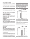
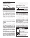
discharge opening must not be blocked or reduced in size under
anycircumstances.Excessivelength,over30feet(9.14m),or
use of more than four elbows can cause restriction and reduce
the discharge capacity of the valve.
No valve or other obstruction is to be placed between the
Temperature-Pressure Relief Valve and the tank. Do not connect
discharge piping directly to the drain unless a 6” (15.2 cm)
air gap is provided. To prevent bodily injury, hazard to life, or
property damage, the relief valve must be allowed to discharge
water in adequate quantities should circumstances demand. If
the discharge pipe is not connected to a drain or other suitable
means,thewaterowmaycausepropertydamage.
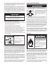
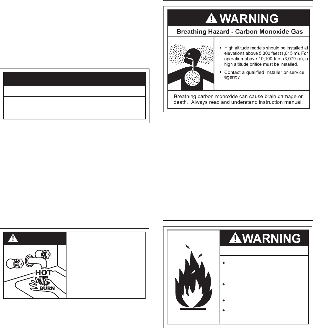
CAUTION
• Temperature-Pressure Relief Valve discharge
pipe must terminate at adequate drain.
Water Damage Hazard
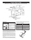
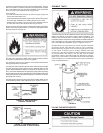
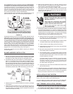
T&P Valve Discharge Pipe Requirements:
• Shouldnotbesmallerinsizethantheoutletpipesizeofthevalve,or
have any reducing couplings or other restrictions.
• Shouldnotbepluggedorblocked.
• Shouldnotbeexposedtofreezingtemperatures.
• Shouldbeofmateriallistedforhotwaterdistribution.
• Shouldbeinstalledsoastoallowcompletedrainageofboththe
Temperature-Pressure Relief Valve and the discharge pipe.
• Mustterminateamaximumofsixinchesaboveaoordrainorexternal
to the building. In cold climates, it is recommended that the discharge
pipe be terminated at an adequate drain inside the building.
• Shouldnothaveanyvalveorotherobstructionbetweentherelief
valve and the drain.
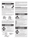
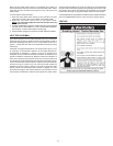
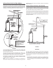
DANGER
• Burn hazard.
• Hot water discharge.
• Keep clear of Temperature-
Pressure Relief Valve
discharge outlet.
The Temperature-Pressure Relief Valve must be manually operated
atleasttwiceayear.Cautionshouldbetakentoensurethat(1)no
one is in front of or around the outlet of the Temperature-Pressure
ReliefValvedischargeline,and(2)thewatermanuallydischarged
will not cause any bodily injury or property damage because the
water may be extremely hot. If after manually operating the valve, it
fails to completely reset and continues to release water, immediately
close the cold water inlet to the water heater, follow the draining
instructions in this manual, and replace the Temperature-Pressure
Relief Valve with a properly rated/sized new one.
NOTE: The purpose of a Temperature-Pressure Relief Valve is to
prevent excessive temperatures and pressures in the storage tank.
The T&P valve is not intended for the constant relief of thermal
expansion. A properly sized thermal expansion tank must be installed
on all closed systems to control thermal expansion, see Closed Water
Systems and Thermal Expansion on page 15-16.
If you do not understand these instructions or have any questions
regarding the Temperature-Pressure Relief Valve call the toll free number
listed on the back cover of this manual for technical assistance.
HIGH ALTITUDE INSTALLATION
Thisheaterisapprovedforoperationupto5,300feet(1,615m)
without alteration. High altitude models are available from the factory
forelevationsbetween5,300feet(1,615m)and10,100feet(3,079
m).Forelevationsabove10,100feet(3,079m)theinputrating
shouldbereducedattherateof4percentforeach1,000feet(305
m)abovesealevelwhichrequiresreplacementoftheburneroricein
accordancewithNationalFuelGasCode(ANSIZ223.1/NFPA54)or
theNaturalGasandPropaneInstallationCode(CAN/CSAB149.1).
Contact your local gas supplier for further information.
Failuretoreplacestandardoricewithahighaltitudeoricewheninstalled
above10,100feet(3,079m)couldresultinimproperandinefcient
operation of the appliance, producing carbon monoxide gas in excess of
safe limits, which could result in serious injury or death. Contact your gas
supplierforanyspecicchangeswhichmayberequiredinyourarea.
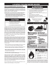
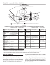
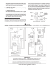
GAS PIPING
Fire and Explosion Hazard
Do not use water heater with any
gas other than the gas shown on
the rating plate.
Excessive pressure to gas control
valve can cause serious injury or death
Turn off gas lines during installation.
Contact qualified installer or
service agency.
Make sure the gas supplied is the same type listed on the model rating
plate.Theinletgaspressuremustnotexceed14inchwatercolumn(3.5
kPa)fornaturalandpropanegas(L.P.).Theminimuminletgaspressure
shownontheratingplateisthatwhichwillpermitringatratedinput.
All gas piping must comply with local codes and ordinances or with the
NationalFuelGasCode(ANSIZ223.1/NFPA-54)ortheNatural
GasandPropaneInstallationCode(CAN/CSAB149.1)whichever
applies.Copperorbrasstubingandttings(excepttinlinedcopper
tubing)shouldnotbeused.
If the gas control valve is subjected to pressures exceeding 1/2 psi
(3.5kPa),thedamagetothegascontrolvalvecouldresultinare
or explosion from leaking gas.
If the main gas line Shut-off serving all gas appliances is used, also
turn“off”thegasateachappliance.Leaveallgasappliancesshut
“off”untilthewaterheaterinstallationiscomplete.


