


11
OF ELECTRICAL SHOCK. DO NOT ENERGIZE THE BRANCH
CIRCUIT BEFORE THE HEATER TANK IS FILLED WITH
WATER.
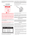
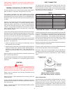
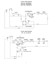
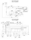
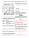
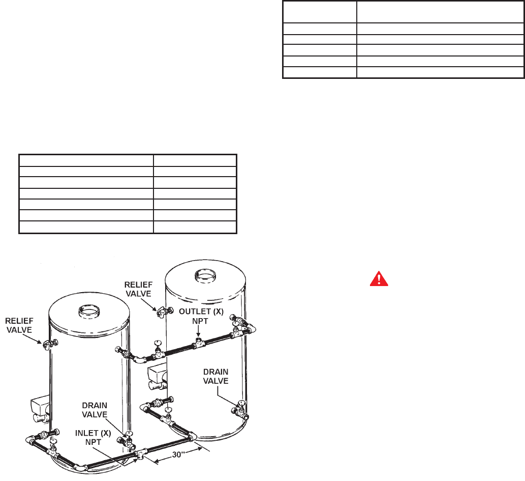
TWO UNIT MANIFOLD
INSTALLATION
Assure water flow balance of all units. Without this balance, the
full water heating and storage potential of the system cannot be
achieved. Otherwise, the units with the higher water flow may
have a shortened life.
Dimensions shown are for minimum space occupied by complete
assemblies. Service space in front of units must be included.
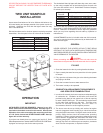
MODEL MANIFOLD SIZE
BTPD-85 2”
BTPN/BTP/COF/COBT - 140 2”
BTPN/BTP/COF/COBT - 200 2 1/2”
BTPN/BTP/COF/COBT - 300 2 1/2”
BTPN/BTP/COF/COBT - 400 3”
BTPN/BTP/COF/COBT - 600 3”
OPERATION
IMPORTANT
AUTHORIZED START-UP REQUIRED. Start-up by an A.O.
Smith Authorized BTP/BTPN/COF/COBT Start-Up Agent is
required on the models covered in this manual. Start-up and
Operation of the units covered by this manual by other than
an A.O. Smith Authorized BTP/BTPN/COF/COBT Start-Up
Agent will void the warranty.
If you have not already done so, contact your local A.O. Smith
Sales Representative or Authorized BTP/BTPN/COF/COBT Start-
Up Agent and set-up a date for the start-up service.
The Authorized Start-Up Agent will when they come out to start-
up the unit(s) complete one of the following forms for each unit
you have and submit it to A.O. Smith Water Products Company
to activate your warranty:
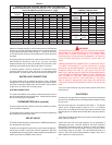
Start-Up Covering Models
Form No.
09063511 BTP Models, 140 - 255 kBTUH
09063510 BTP Models, 270 - 2500 kBTUH
09063512 COBT Models, 140 - 2500 kBTUH
09063514 COF Models, 140 - 2500 kBTUH
09063515 BTPN Models, 400 - 2000 kBTUH
The time to ask any questions you may have about your unit is
when the A.O. Smith Authorized BTP/COF/COBT Start-Up Agent
is there. Please do not hesitate to ask the agent any questions
which you may have regarding the units start-up, operation or
maintenance.
A MAINTENANCE section is included at the rear of this manual.
Any service required should be performed by an Authorized A.O.
Smith Service Agent.
GENERAL
NEVER OPERATE THE HEATER WITHOUT FIRST BEING
CERTAIN IT IS FILLED WITH WATER AND A TEMPERATURE
AND PRESSURE RELIEF VALVE IS INSTALLED IN THE RELIEF
VALVE OPENING OF THE HEATER.
CAUTION
Before proceeding with the operation of the unit make sure the
water heater and system are filled with water and all air is expelled.
FILLING
1. Close the heater drain valve by turning handle clockwise.
2. Open a nearby hot water faucet to permit the air in the system
to escape.
3. Fully open the cold water inlet pipe valve allowing the heater
and piping to be filled.
4. Close the hot water faucet as water starts to flow.
5. The heater is ready to be operated.
COMBUSTION ARRANGEMENT REQUIREMENTS
AND SERVICE RECOMMENDATIONS
1. In order to fire correctly, the burner requires an adequate supply
of combustion air. Ventilation to the boiler room should be
provided on the basis of one square inch of free air opening
for each 1000 BTU/HR input. This excludes the requirements
for any other fired equipment in the room. The boiler room
should not become excessively hot and under no
circumstances should be under negative pressure.
2. The burner must be set up initially and serviced at regular
intervals (suggested semi-annually) by a trained serviceman
using the proper instruments. During this semi-annual service,
primary safety devices should be tested under operating
conditions. Failure to routinely test primary safety devices may
cause hazards. Suggested test procedures are listed in the
following paragraphs. Failure to maintain the correct burner
settings may result in inefficient gas consumption, premature
wear of burner components, or explosion hazard.