


15
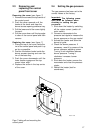
2.1.3 Gas connection
The gas supply to this appliance must
be installed in accordance with BS 6891
(1988) and British Gas Publications UP1
and UP2.
Fit the 1/2” gas supply cock supplied
with this unit immediately before the gas
control. No heat or soldered joints
should be applied in the vicinity of the
gas control, as they could cause
damage to the control. All connections
and joints should be tested for gas
soundness with a suitable leak detector
(do not use a naked flame).
N.B. When operating this unit on LPG a
suitable gas supply cock should be
used.
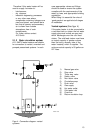
2.1.4 Flue system
The water heater should be fitted with a
flue system connected to the draught
diverter. The flue pipe should rise for at
least 50 cm. vertically before the
inclusion of any bends. If a horizontal
run of flue is required this should be
kept to the minimum lenght possible and
incorporate a rise of 6 cm. per metre of
run. A split clip or flange should be
provided in the flue close to the draught
diverter for ease of servicing.
All flue materials should be corrosion
resident i.e. stainless steel or
galvanised and must include a tested
and apprved terminal to BS 5440 part 1.
If the flue passes through any
combustible marerial measures must be
taken to protect against the possibility of
fire.
All flues must terminate in free air space
approx. 1,5 metres from any vertical
surface of structure i.e. chimney
stacks, roof parapets, etc. If an existing
chimney or flue is to be used this should
be swept clean and be free of debris
before an approved liner is installed and
connected to the water heater.
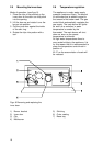
2.1.5 Draught diverter
The appliance has been fitted with a
flue down draught safety device. The
operation of the safeguard is based on
the principle of the Thermal Reflux
Safeguard (TRS).
This TRS can be recognized by the
copper coloured spiral that is fitted to
the lower edge of the draught diverter.
The spiral is connected to a thermostat
by means of a capillary tube. The wiring
of the thermostat must be connected to
the thermocouple circuit.
Important
The TRS should never be put out of
operation. The reentry of flue
gasses may cause poisoning.
2.1.6 Electrical connection
All electrical connections must be
carried out in accordance with IEE
regulations by an accredited electrical
installation company. The appliance
must be connected to the mains by
means of a permanent electrical
connection. A main switch must be
fitted in the phase between the perma-
nent connection and the water heater.
The feeder cable must have cores of at
least 3 * 1.0 mm
2
The connecting clamps
for the electricity supply are indicated
by the symbol for earth Á, N for neutral
and L for live. Always check with a vol-
tage tester if the live and the neutral
have been connected correctly in the
electricity supply. The electricity supply
must comply with the requirements
below:
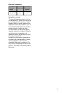
Electrical Frequency Electrically
supply fused to a
minimum of
220/240 V AC 50 Hz 5A
The maximum power consumption is
25 W
See electrical diagram for more
information, appendix 1.