


6
2. Toxic chemicals, such as those used for boiler treatment, shall
NEVER be introduced into this system.
3. This unit may NEVER be connected to any existing heating
system or component(s) previously used with a non-potable
water heating appliance.
4. When the system requires water for space heating at
temperatures higher than required for domestic water
purposes, a tempering valve must be installed (See Fig. 3).
CAUTION
A closed system will exist if a check valve (without bypass), pressure
reducing valve (without bypass), or a water meter (without bypass)
is installed in the cold water line between the water heater and
street main (or well).
Excessive pressure may develop in such closed systems, causing
premature tank failure or intermittent relief valve operation.
This is
not a warranty failure. An expansion tank or a similar device may
be required in the inlet supply line between the appliance and the
meter or valve to compensate for the thermal expansion of the
water.
SYSTEM CONNECTIONS
The system installation must conform to these instructions and to
the local code authority having jurisdiction. Good practice requires
that all heavy piping be supported.
VENTING
WARNING
THE INSTRUCTIONS IN THIS SECTION ON VENTING MUST BE
FOLLOWED TO AVOID CHOKED COMBUSTION OR
RECIRCULATION OF FLUE GASES. SUCH CONDITIONS CAUSE
SOOTING OR RISKS OF FIRE AND ASPHYXIATION.
Heater must be protected from freezing downdrafts.
Remove all soot or other obstructions from the chimney that will
retard a free draft.
Type B venting is recommended with these heaters.
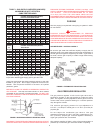
This water heater must be vented in compliance with all local
codes, the current revision of the National Fuel Gas Code
(ANSI-Z223.1) and with the Category I Venting Tables. In Canada,
venting shall conform to the requirements of the current CAN/CSA
B149.1-00 installation code.
If any part of the vent system is exposed to ambient temperatures
below 35 degrees F (2 degrees C) it must be insulated to prevent
condensation.
• Do not connect the heater to a common vent or chimney with
solid fuel burning equipment. This practice is prohibited by
many local building codes as is the practice of venting gas
fired equipment to the duct work of ventilation systems.
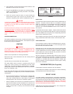
• Where a separate vent connection is not available and the vent
pipe from the heater must be connected to a common vent
with an oil burning furnace, the vent pipe should enter the
smaller common vent or chimney at a point above the large
vent pipe.
FIGURE 2
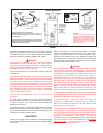
DRAFT HOOD
The draft hood furnished with this heater must be installed without
alteration. Provision must be made if it is installed in confined
space or a small room to accommodate draft hood spillage and
avoid risks described in previous steps. The upper air opening
called for in the AIR REQUIREMENTS section of this manual is for
this purpose.
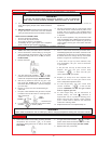
Locate draft hood as seen in Figure 1. Position draft hood over the
flue tube. Align the draft hood legs with four holes surrounding the
flue. Insert tabbed end of legs into the corresponding holes and
twist to lock the draft hood in place.
When installing vent piping, secure the vent pipe to the draft hood
using at least three sheet metal screws in the draft hood outlet.
VENT CONNECTION
Vent connections must be made to an adequate stack or chimney.
Size and install proper size vent pipe. Do not reduce pipe size to
less than that of the draft hood outlet.
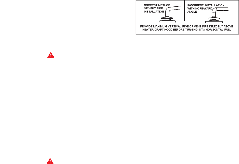
Horizontal runs of vent pipe must have a minimum upward slope
toward the chimney of 1/4 inch per foot (20 mm per meter). Dampers
or other obstructions must not be installed in between the heater
and the draft hood. Be sure that the vent pipe does not extend
beyond the inside wall of the chimney.
Where a continuous or intermittent back draft is found to exist, the
cause must be determined and corrected. A special vent cap may
be required. If the back draft cannot be corrected by the normal
methods or if a suitable draft cannot be obtained, a blower type
flue gas exhauster must be employed to assure proper venting
and correct combustion.
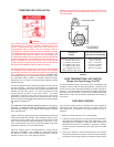
THERMOMETERS (Not Supplied)
Thermometers should be obtained and field installed.
Thermometers are installed in the system as a means of detecting
the temperature of the outlet water supply.
RELIEF VALVE
This water heater is equipped with a combination temperature-
pressure relief valve that complies with the standard for relief valves
and automatic gas shut-off devices for hot water supply system,
ANSI Z21.22, for Canada see CAN/CSA 149.1-00.
FOR SAFE
OPERATION OF THE WATER HEATER, THE RELIEF VALVE(S)
MUST NOT BE REMOVED OR PLUGGED.
ASME ratings cover pressure relief capacities. A.G.A. ratings cover
release rate with temperature actuation.