


www.aosmithinternational.com
X
Y
V
W
W
Y
V
X
X1
Y1
V
W
X2
Y2
V
W
W
Y
V
X
BFM 30-80
BFM 100-120
Data subject to change INT/1108/BFM/02
Terms and conditions apply, please refer to our website.
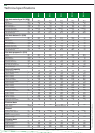
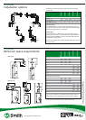
Flue systems BFM
Installation options
Concentric x x x - -
Parallel - - - x x
Diameter (mm) 80/125 100/150 130/200 2 x 130 2 x 130
Max. length (m) 7 7 7 7 7
Max. 45/90° bends a pipe 2 2 2 2 2
Concentric flues
It is not permitted to use more than the specified number of
bends, even when the duct is shorter than the maximum length.
A 45° bend is equivalent to a 90° bend.
Parallel flues
The parallel flue of a BFM 100 of 120 unit should always be
connected to the wall or roof penetration using the standard
transition piece (0306801). The two ducts shall not terminate
in different pressure zones.
Note: horizontal flue runs must be installed with a fall of at least
5 mm per metre.
BFM 30
BFM 50
BFM 80
BFM 100
BFM 120
A BFM water heater should be installed according category
C13 or C33.
C13 C13
C33 C33
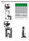
Flue systems BFM
Minimum space requirements
Minimal space for wall duct (mm)
V 550 550 640
W 725 790 940
X 2115 2165 2190
Y 1195 1215 1310
Y * 745 765 860
V 700 700
W 1000 1000
X1 2480 2480
Y1 955 955
X2 2140 2140
Y2 1320 1320
Y2 * 870 870
Minimal space for roof duct (mm)
V 1230 1310 1610
W 605 645 1000
X 3575 3615 3580
Y 1575 1615 1560
Y ** 625 665 610
V 2560 2560
W 1000 1000
X 3580 3580
X ** 2630 2630
Y 1560 1560
Y ** 610 610
For the parts numbers of components and flue gas ducts, etc.
please refer to the “Maintenance and accessories” chapter.
BFM 30
BFM 50
BFM 80
BFM 100
BFM 120
Ø80/125 Ø100/150 Ø130/200 2 x Ø130 2 x Ø130
* Distance without concentric pipe between bend and wall duct.
** Distance without concentric pipe between appliance and roof duct.