


Cyclone BFC
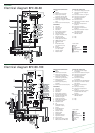
Electrical diagram BFC 28-60
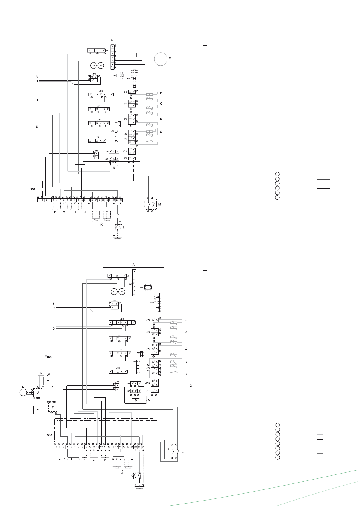
Cyclone BFC
Electrical diagram BFC 80-100
TERMINAL STRIP CONNECTIONS
Earth
N Neutral
L Phase input of controller
L1 Phase output of isolating
transformer ( secundary side)
L2 Phase input of isolating
transformer ( primary side)
L3 Phase input of program-
controlled pump
L4 Phase input of frequency
controller
L5 Phase input of continuous pump
COMPONENTS
A Controller
B Ionisation rod
C Glow ignitor
D Gas control
E Burner earth connection
F External ON-mode switch
G Program-controlled pump
H External error-signal
J Isolating transformer
K Double-pole mains switch
L Controller 0/1 switch
M Display/Flat cable
N Fan
O Temperaturesensor
(T2-bottom of tank)
P Dummy
Q Temperaturesensor
(T1-top of tank)
R Selection resistor
S Pressure switch
T Potentiostat
U Frequency controller
V Argus-link interface
W Electric anodes
X Signaling for electric anodes
Y Mains choke and EMC filter
CONTROLLER CONNECTIONS
J2 Connector for power supply
to controller
J19 Connector for external error-signal
J20 Connector for gas-control
J21 Connector for program
controlled pump
J36 Connector for display
to controller
J39 Connector for fan controlled signal
JP2 Connector for ionisation rod and
glow ignitor
JP3 Connector for temperature
sensor T2
JP4 Connector for dummy
JP5 Connector for temperature
sensor T1
JP6 Connector for selection resistor,
pressure switch and anode
signaling
JP8 Connector for extra
ON-mode switch
F1 Fuse
F3 Fuse
TERMINAL STRIP CONNECTIONS
Earth
N Neutral
L1 Phase input of controller
L2 Phase input of isolating
transformer (primary side)
L3 Phase output of isolating
transformer (secondary side)
L4 Phase input of program-controlled
pump
L5 Phase input of continuous pump
COMPONENTS
A Controller
B Ionisation rod
C Glow igniter
D Gas control
E Burner earth connection
F Extra ON mode switch
G Continuous pump
H Program-controlled pump
J Extra error signal
K Isolating transformer
L Double-pole mains switch
M ON/OFF switch control
N Display/Flat cable
O Fan
P Temperature sensor
(T2 - bottom of tank)
Q Dummy
R Temperature sensor
(T1 - top of tank)
S Selection resistor
T Pressure switch
CONTROLLER CONNECTIONS
J1 Connector for display to controller
J2 Connector for power supply to
controller
J19 Connector for extra error signal
J20 Connector for gas control
J21 Connector for program-
controlled pump
J24 Connector for fan
JP2 Connector for ionisation rod and
glow igniter
JP3 Connector for temperature
sensor T2
JP4 Connector for dummy
JP5 Connector for temperature
sensor T1
JP6 Connector for selection resistor
and pressure switch
JP8 Connector for extra
ON mode switch
F1 Fuse
F2 Fuse
Colour cables
1 = brown
2 = blue
3 = yellow/green
4 = black
5 = white (flat cable)
6 = grey/beige
Colour cables
1 = brown
2 = blue
3 = yellow/green
4 = black
5 = white (flat cable)
6 = grey/beige
7 = red
8 = green