


Instruction manual BFC 91
is
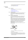
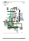
TERMINAL BLOCK CONNECTIONS:
Earth
N Neutral
L Phase input of controller
L
1
Phase output of isolating transformer (secondary side)
L
2
Phase input of isolating transformer (primary side)
L
3
Phase input of program-controlled pump
L
4
Live input of frequency controller
L
5
Phase input of continuous pump
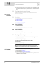
COMPONENTS:
A Controller
B Flame probe
C Hot surface igniter
D Gas control
E Burner earth connection
F Extra ON mode switch
G Program-controlled pump
H External error signal connection
J Isolating transformer
K Double-pole isolator
L Controller 0/I switch
M Display
NFan
O Temperature sensor (T2 - bottom of tank)
P Dummy
Q Temperature sensor (T1 - top of tank)
R Selection resistor
S Pressure switch
T Potentiostat
U Frequency controller
V RS-485 interface
W Electrical anodes
X Signalling for electrical anodes
KY Mains power choke and EMC filter
CONTROLLER CONNECTIONS:
J2 Power connection for controller
J19External error signal connection
J20Gas control connection
J21Program-controlled pump connection
J36Controller display connection
J39Fan control signal connection
JP2Flame probe and hot surface igniter connection
JP3Temperature sensor T2 connection
JP4Dummy connection
JP5Temperature sensor T1 connection
JP6Connection for selection resistor, pressure switch and
anode signalling
JP8Extra ON mode switch connection
F1 Fuse
F3 Fuse