


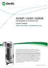
ADMP / ADM / ADMR
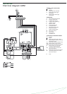
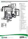
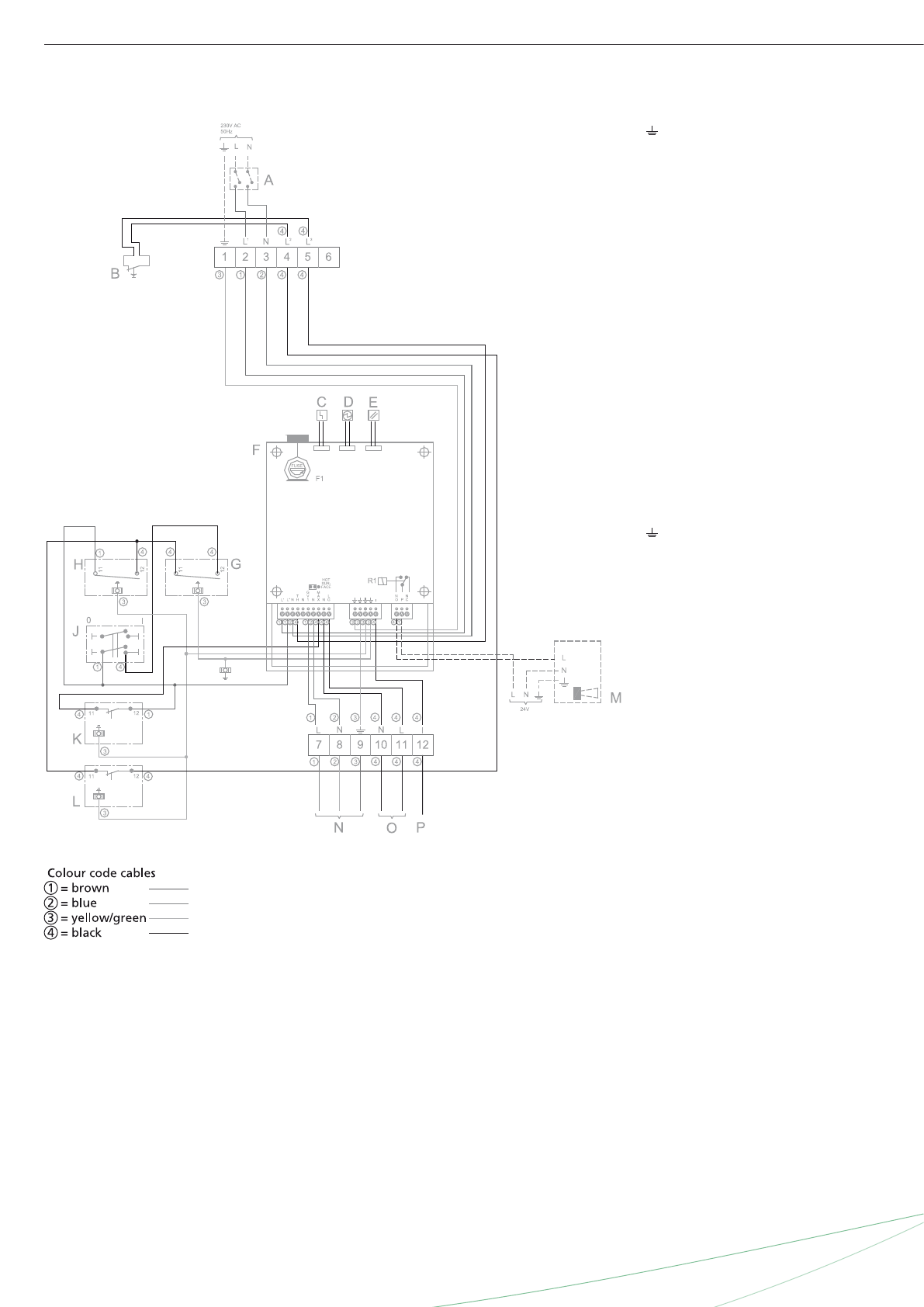
Electrical diagram ADM
TERMINAL STRIP CONNECTIONS
Earth
N Neutral
L1 Phase input of controller
L2 Phase input of flue gas
thermostat
L3 Phase output of flue gas
thermostat
COMPONENTS
A Two-terminal main switch
B Flue gas thermostat
C Indicator LED “Error”
D Indicator LED “Running”
E “RESET” button
F Burner control
G Control thermostat
H Frost thermostat
J 0/1 switch of controller
K Safety thermostat
L High-limit thermostat
M Extra error sensor
N Gas control
O Glow igniter
P Ionisation rod
CONNECTIONS ON BURNER CONTROL
N1 Neutral
Earth
L’ Phase input of burner control
L” Phase output to safety circuit and
thermostat circuit
TH Phase input of thermostat circuit
GV1 Phase output to gas control
MAX Phase input of safety thermostat
LG Phase output to glow igniter
I Ionisation signal detection
NO “Normally open” port of the
extra error sensor
P Phase input of extra error sensor
NC “Normally closed” port of the
extra error sensor
F1 Fuse