


Conversion to a different gas category
38 Instruction manual ADM
4
is
1. Carry out (4.1 "Conversion to different category ADM 40 through 115") steps
1 through 10 .
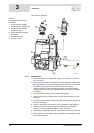
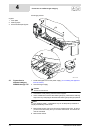
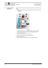
2. Detach the high-low control (9).
3. Fit the burner pressure regulator (1) including the sealing gasket from the
conversion kit. Attach the burner pressure regulator to the gas control using
the two small screws supplied (7).
4. Detach the leads between the 6contact terminal strip(6) and the 9contact
terminal strip (8). These are the leads for the timers, high-low control, gas
control, hot surface igniter and flame probe.
5. Remove the timers (4), bracket (5), wiring harness (not shown) and 9contact
terminal strip.
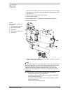
6. Turn the metric strain relief (9) with the high-low control lead (10) to loosen
it. Remove this lead.
7. Fit the stop plug from the conversion set in the place of the metric strain
relief.
8. Connect the cables of the gas control, the hot surface igniter and flame
probe to the 6contact terminal strip as indicated in the electrical
diagram (14.2 "Electrical Diagrams ADM").
9. Clamp the gas control cable in one of the supplied strain reliefs (7). Do the
same for the leads of the hot surface igniter and flame probe.
10. Check the supply pressure and burner pressure (3.11 "Checking the supply
pressure and burner pressure").
11. Remove the sticker showing the new gas category from the conversion kit,
and attach it below the appliance's rating plate. This clearly indicates that the
appliance may no longer be run on the gas for which it was originally
supplied.
12. Start the appliance (9 "Starting and running").
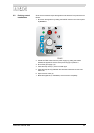
4.2.3 Conversion from natural gas to LP gas
1. Carry out steps 1 through 10 (4.1 "Conversion to different category ADM 40
through 115").
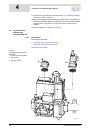
2. Detach the burner pressure regulator (1).
3. Fit the high-low controller (9) including the sealing gasket from the
conversion set. Attach the high-low control to the gas control using two small
screws.
4. Detach the leads from the gas control, the hot surface igniter and the flame
probe to the 6contact connector strip (6) and the strain relief (7).
5. Fit the timers (4) including cable harness plus 9contact terminal strip (6)
from the conversion kit to the control column.
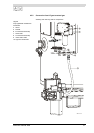
6. Remove the stop plug (not shown) from the underside of the control column
and replace this with the metric strain relief (9) from the conversion kit.
7. Draw the high-low control lead (10) through the strain relief and tighten the
strain relief by turning it until the lead is clamped.
8. Connect the high-low control lead (10) plug to the high-low control (9).
9. Connect the cables from the timers, highlow control, gas control and the hot
surface igniter as shown in the electrical diagram (14.2 "Electrical Diagrams
ADM").
10. Check the supply pressure and burner pressure (3.11 "Checking the supply
pressure and burner pressure").